- VSV for air injection system circuit (bank 1)
- Vacuum hose (VSV for air injection system - No. 2 air switching valve)
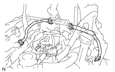
- Air injector pipe (No. 2 air switching valve - exhaust manifold)
- No. 2 air switching valve (bank 1)
- VSV for air injection system (bank 1)
- ECM
| Last Modified: 4-30-2014 | 6.6 C | Doc ID: RM000001BRG002X |
| Model Year: 2006 | Model: LX470 | Prod Date Range: [05/2005 - ] |
| Title: 2UZ-FE ENGINE CONTROL SYSTEM: SFI SYSTEM: P1442,P1445,P2441; Stuck Close in Secondary Air Injection Vacuum Switching Valve Bank 1; 2006 MY LX470 [05/2005 - ] | ||
|
DTC |
P1442 |
Stuck Close in Secondary Air Injection Vacuum Switching Valve Bank 1 |
|
DTC |
P1445 |
Stuck Close in Secondary Air Injection Vacuum Switching Valve Bank 2 |
|
DTC |
P2441 |
Secondary Air Injection System Switching Valve Stuck Close Bank1 |
DESCRIPTION
Refer to DTC P0412
![2006 MY LX470 [05/2005 - ]; 2UZ-FE ENGINE CONTROL SYSTEM: SFI SYSTEM: P0412; Secondary Air Injection System Switching Valve "A" Circuit+](../../../../stylegraphics/info.gif "2006 MY LX470 [05/2005 - ]; 2UZ-FE ENGINE CONTROL SYSTEM: SFI SYSTEM: P0412; Secondary Air Injection System Switching Valve \"A\" Circuit+") .
.
|
DTC No. |
DTC Detection Condition |
Trouble Area |
|---|---|---|
|
P1442 |
No. 2 air switching valve (bank 1) stuck closed: No pressure change (decrease) after the ECM sends an open No. 2 air switching valve (bank 1) signal. (2 trip detection logic) |
|
|
P1445 |
No. 2 air switching valve (bank 2) stuck closed: No pressure change (decrease) after the ECM sends an open No. 2 air switching valve (bank 2) signal. (2 trip detection logic) |
|
|
P2441 |
Air switching valve stuck closed: The pressure sensor does not detect exhaust pulsation when system operates. (All of air switching valve ON) This DTC means either of the following conditions is met.
|
|
MONITOR DESCRIPTION
Refer to DTC P1441, P1444 and P2440
.
MONITOR STRATEGY
|
Related DTCs |
(Case 1) P1442 AIR VSV stuck close bank 1 (Case 2) P1445 AIR VSV stuck close bank 2 (Case 3) P2441 AIR valve stuck close |
|
Required sensors/Components |
AIR pressure sensor, AIR valve, AIR VSV bank 1, AIR VSV bank 2 |
|
Frequency of operation |
Once per driving cycle |
|
Duration |
Within 60 seconds |
|
MIL operation |
2 driving cycles |
|
Sequence operation |
None |
TYPICAL ENABLING CONDITIONS
Common conditions
|
This monitor runs whenever these DTCs are not present |
|
|
Atmospheric pressure |
45 kPa or higher |
|
Battery voltage |
11.5 V or higher |
|
Sequence 1 - 5 are performed to monitor AIR |
- |
|
[Sequence 1] |
- |
|
Idle |
ON |
|
AIR |
In operation |
|
AIR pump |
ON |
|
AIR valve |
ON |
|
AIR VSV bank 1 |
ON (OFF) |
|
AIR VSV bank 2 |
OFF (ON) |
|
[Sequence 2] |
- |
|
Idle |
ON |
|
AIR |
In operation |
|
AIR valve |
ON |
|
AIR VSV bank 1 |
ON |
|
AIR VSV bank 2 |
ON |
|
[Sequence 3] |
- |
|
Engine RPM |
Less than 3,750 rpm |
|
AIR |
In operation |
|
AIR pump |
ON |
|
AIR valve |
ON |
|
AIR VSV bank 1 |
ON |
|
AIR VSV bank 2 |
ON |
|
[Sequence 4-a] |
Performed when AIR pressure changes at sequence 2 |
|
Engine RPM |
Less than 3,750 rpm |
|
AIR |
Not operating |
|
AIR pump |
OFF |
|
AIR valve |
OFF |
|
AIR VSV bank 1 |
OFF |
|
AIR VSV bank 2 |
OFF |
|
[Sequence 4-b] |
Performed when AIR pressure does not change at sequence 2 |
|
Engine RPM |
Less than 3,750 rpm |
|
AIR |
Not operating |
|
AIR pump |
ON |
|
AIR valve |
ON |
|
AIR VSV bank 1 |
ON (OFF) |
|
AIR VSV bank 2 |
OFF (ON) |
|
[Sequence 5] |
- |
|
Engine RPM |
Less than 3,750 rpm |
|
AIR |
Not operating |
|
AIR pump |
OFF |
|
AIR valve |
ON |
|
AIR VSV bank 1 |
OFF |
|
AIR VSV bank 2 |
OFF |
TYPICAL MALFUNCTION THRESHOLDS
Thresholds for Case 1
|
Averaged AIR pressure at sequence 3 |
More than 1 kPa |
|
Cumulative AIR pressure pulse at sequence 3 |
More than 15 kPa |
|
Averaged AIR pressure at sequence 5 |
Less than 5 kPa |
|
Cumulative AIR pressure pulse at sequence 5 |
Less than 30 kPa |
Thresholds for Case 2
|
Averaged AIR pressure at sequence 3 |
More than 1 kPa |
|
Cumulative AIR pressure pulse at sequence 3 |
More than 15 kPa |
|
Averaged AIR pressure at sequence 5 |
Less than 5 kPa |
|
Cumulative AIR pressure pulse at sequence 5 |
Less than 30 kPa |
Thresholds for Case 3
|
Averaged AIR pressure at sequence 3 |
More than 1 kPa |
|
Cumulative AIR pressure pulse at sequence 3 |
Less than 15 kPa |
|
Averaged AIR pressure at sequence 5 |
Less than 5 kPa |
|
Cumulative AIR pressure pulse at sequence 5 |
Less than 30 kPa |
MONITOR RESULT
Refer to CHECKING MONITOR STATUS
.
|
Monitor ID |
Test ID |
Scaling |
Unit |
Description |
|---|---|---|---|---|
|
$71 |
$E1 |
Multiply by 0.01 |
g/sec. |
AIR amount for AIR insufficient |
|
$71 |
$E2 |
Multiply by 0.01 |
kPa |
Averaged AIR pressure for AIR pump ON stuck |
|
$71 |
$E3 |
Multiply by 0.01 |
kPa |
Averaged AIR pressure for AIR pump OFF stuck |
|
$71 |
$E4 |
Multiply by 0.01 |
kPa |
AIR pressure pulse for AIR valve and AIR VSV open stuck |
|
$71 |
$E5 |
Multiply by 0.01 |
kPa |
AIR pressure pulse for AIR valve and AIR VSV close stuck |
|
$71 |
$E6 |
Multiply by 0.01 |
kPa |
AIR pressure difference for AIR valve |
|
$71 |
$E7 |
Multiply by 0.01 |
kPa |
AIR pressure difference for AIR VSV bank 1 |
|
$71 |
$E8 |
Multiply by 0.01 |
kPa |
AIR pressure difference for AIR VSV bank 2 |
|
$71 |
$E9 |
Multiply by 0.01 |
kPa |
AIR pressure pulse for AIR VSV stuck open bank 1 and bank 2 |
WIRING DIAGRAM
Refer to DTC P0412
.
INSPECTION PROCEDURE
HINT:
Read freeze frame data using the intelligent tester. Freeze frame data records the engine conditions when malfunctions are detected. When troubleshooting, freeze frame data can help determine if the vehicle was running or stopped, if the engine was warmed up or not, if the air fuel ratio was lean or rich, and other data from the time the malfunction occurred.
PROCEDURE
|
1. |
CHECK ANY OTHER DTCS OUTPUT (IN ADDITION TO SECONDARY AIR INJECTION SYSTEM DTCS) |
(a) Connect the intelligent tester to the CAN VIM. Then connect the CAN VIM to the DLC3.
(b) Turn the ignition switch ON and turn the tester ON.
(c) Enter the following menus: DIAGNOSIS / ENHANCED OBD II / DTC INFO / CURRENT CODES.
(d) Read DTCs.
Result
|
Display (DTC Output) |
Proceed to |
|---|---|
|
"P1442 and/or P1445" and P2441 |
A |
|
P1442 and/or P1445 |
B |
|
"P1442 and/or P1445 and/or P2441" and other DTCs |
C |
HINT:
If any DTCs other than P1441 and/or P1444 and P2440 are output, troubleshoot those DTCs first.
| B |

|
| C |
|
|

|
2. |
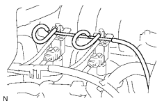
CHECK VACUUM HOSES (THROTTLE BODY - VSV FOR AIR INJECTION SYSTEM) |
|
(a) Check that the vacuum hoses between the throttle body and VSV for air injection system are securely connected. OK: The vacuum hoses are securely connected. (b) Inspect the vacuum hoses for blockages and damage. OK: The vacuum hoses have no blockages and damage. |
|
| NG |
|
|
|
3. |
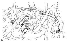
CHECK PIPES AND HOSES (CONNECTION OF AIR INJECTION SYSTEM) |
|
(a)
Remove the intake manifold
(b) Check all pipes and hoses of the air injection system. OK: All air injection pipes and hoses are securely connected. (c) Check all pipes and hoses for blockage or damage. OK: All air injection pipes and hoses have no blockages and damage. |
|
| NG |
|
|
|
4. |
CHECK AIR SWITCHING VALVE (OPERATION) |
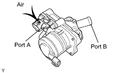
(a)
Remove the intake manifold
.
(b) Remove the Air Switching Valve (ASV).
(c) Blow air into port A and check that air is not discharged from port B.
OK:
Not discharged
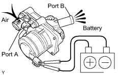
(d) Apply battery positive voltage across the terminals.
(e) Blow air into port A and check that air is discharged from port B.
OK:
Discharged
| NG |
|
|
|
5. |
CHECK NO. 2 AIR SWITCHING VALVE (OPERATION) |
|
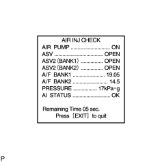
(a) Start the engine and warm it up. (b) Turn the ignition switch OFF. (c) Connect the intelligent tester to the CAN VIM. Then connect the CAN VIM to the DLC3. (d) Turn the ignition switch ON and push the intelligent tester main switch ON. (e) Enter the following menus: DIAGNOSIS / ENHANCED OBD II / SYSTEM CHECK / AIR INJ CHECK / MANUAL / OPERATION 5 and 6. HINT: OPERATION 5: AP: ON; EASV: OPEN; ASV1: OPEN; ASV2: CLOSE OPERATION 6: AP: ON; EASV: OPEN; ASV1: CLOSE; ASV2: OPEN NOTICE:
(f) Read value of the A/F BANK1 and BANK2 on the intelligent tester.
HINT:
|
|
|
|
6. |
CHECK VSV (FOR AIR INJECTION SYSTEM) |
|
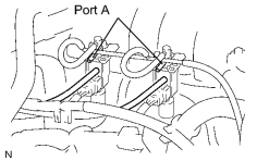
(a) Turn the ignition switch OFF. (b) Disconnect the vacuum hoses from the VSV for air injection system. (c) Connect the intelligent tester to the CAN VIM. Then connect the CAN VIM to the DLC3. (d) Start the engine and turn the tester ON. (e) When the air switching valve is operated using the intelligent tester, check that negative pressure from port A. (f) Enter the following menus: DIAGNOSIS / ENHANCED OBD II / SYSTEM CHECK / AIR INJ CHECK / MANUAL / OPERATION 2. HINT: OPERATION 2: AP: ON; EASV: OPEN; ASV1: OPEN; ASV2: OPEN NOTICE:
OK: Negative pressure from port A (g) Reconnect the vacuum hose. |
|
| NG |
|
|
|
7. |
CHECK VACUUM HOSES (AIR SWITCHING VALVE - VSV FOR AIR INJECTION SYSTEM) |
|
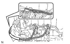
(a) Check that the vacuum hoses between the No. 2 air switching valve(s) and VSV for air injection system are securely connected. OK: The vacuum hose(s) are securely connected. (b) Check the vacuum hoses for blockages and damage. OK: The vacuum hoses have no blockages and damage. |
|
| NG |
|
|
|
8. |
CHECK NO. 2 AIR SWITCHING VALVE (OPERATION) |
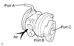
(a) Remove the No. 2 air switching valve.
(b) Blow air into port B and check that air is not discharged from port C.
OK:
Not discharged from port C
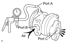
(c) Apply vacuum 30 kPa (225 mmHg) to port A, blow air into port B and check that air is discharged from port C.
OK:
Discharged from port C
| NG |
|
|
|
9. |
CHECK AIR INJECTION PIPE (NO. 2 AIR SWITCHING VALVE - EXHAUST MANIFOLD) |
|
(a) Check that the air injection pipe between the No. 2 air switching valve(s) and exhaust manifold are securely connected. OK: The air injection pipe is securely connected. (b) Check the air injection pipe for blockages and damage. OK: The air injection pipe has no blockages and damage. |
|
| NG |
|
| OK |
|
|
10. |
CHECK VSV (FOR AIR INJECTION SYSTEM) |
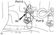
(a) Disconnect the 2 vacuum hoses.
(b) Disconnect the VSV for air injection system connector.
(c) Blow air into port B. Check that air does not flow from port A.
OK:
Air does not flow from port A
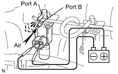
(d) Apply battery positive voltage across the terminals. Then blow air into port B and check that air flows from port A.
OK:
Air flows from port A
| NG |
|
| OK |
|

|

|