| Last Modified: 4-30-2014 | 6.6 J | Doc ID: RM000001BRH000X |
| Model Year: 2006 | Model: LX470 | Prod Date Range: [05/2005 - ] |
| Title: WIPER AND WASHER: WIPER AND WASHER SYSTEM: Rear Wiper Motor Circuit; 2006 MY LX470 [05/2005 - ] | ||
|
Rear Wiper Motor Circuit |
DESCRIPTION
The wiper motor is controlled by the sub body ECU. Even if the CPU is malfunctioning, its circuit structure enables it to operate the wiper in "High" mode.
WIRING DIAGRAM
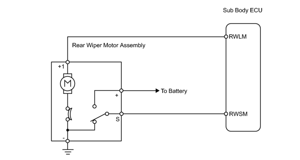
INSPECTION PROCEDURE
HINT:
When using the intelligent tester, start from *1. When not using intelligent tester, start from *2.
PROCEDURE
|
1. |
PERFORM ACTIVE TEST USING INTELLIGENT TESTER (REAR WIPER MOTOR)*1 |
(a) Connect the intelligent tester (with CAN VIM) to the DLC3.
(b)
Check that the rear wiper motor operates in the ACTIVE TEST
![2006 MY LX470 [05/2005 - ]; WIPER AND WASHER: WIPER AND WASHER SYSTEM: DATA LIST / ACTIVE TEST](../../../../stylegraphics/info.gif "2006 MY LX470 [05/2005 - ]; WIPER AND WASHER: WIPER AND WASHER SYSTEM: DATA LIST / ACTIVE TEST") .
.
| OK |

|
PROCEED TO NEXT CIRCUIT INSPECTION SHOWN ON PROBLEM SYMPTOMS TABLE |
|

|
2. |
INSPECT FUSE (RR WIPER) |
(a) Remove the RR WIPER fuse from the cowl side junction block LH.
(b) Measure the resistance of the fuse.
Standard resistance:
Below 1 Ω
| NG |
|
|
|
3. |
CHECK WIRE HARNESS (SUB BODY ECU - BODY GROUND) |
(a) Disconnect the S26 ECU connector.
(b) Turn the ignition switch ON.
(c) Measure the voltage of the wire harness side connector.
Standard voltage:
|
Tester Connection |
Condition |
Specified Condition |
|---|---|---|
|
S26-14 (RWSM) - Body ground |
Except stop position |
6 to 14 V |
|
Stop position |
Below 2 V |
| NG |
|
PROCEED TO NEXT CIRCUIT INSPECTION SHOWN ON PROBLEM SYMPTOMS TABLE |
|
|
4. |
INSPECT REAR WIPER MOTOR ASSEMBLY |
(a)
Inspect the rear wiper motor assembly
.
| NG |
|
|
|
5. |
CHECK SUB BODY ECU |
(a) Measure the voltage of the ECU connector.
Standard voltage:
|
Tester Connection |
Condition |
Specified Condition |
|---|---|---|
|
S26-1 (RWLM) - Body ground |
Ignition switch ON |
10 to 14 V |
| NG |
|
PROCEED TO NEXT CIRCUIT INSPECTION SHOWN ON PROBLEM SYMPTOMS TABLE |
| OK |
|

|

|