| Last Modified: 4-30-2014 | 6.6 J | Doc ID: RM000001BTQ002X |
| Model Year: 2006 | Model: LX470 | Prod Date Range: [05/2005 - ] |
| Title: BRAKE CONTROL: VEHICLE STABILITY CONTROL SYSTEM: ABS Warning Light Circuit; 2006 MY LX470 [05/2005 - ] | ||
|
ABS Warning Light Circuit |
DESCRIPTION
If the ECU detects trouble, it lights the ABS warning light while at the same time prohibiting ABS control. At this time, the ECU records a DTC in memory.
Connect terminals TC and CG of DLC3 to make the ABS warning light blink and output the DTC.
WIRING DIAGRAM
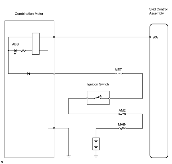
INSPECTION PROCEDURE
HINT:
- When using the intelligent tester, start form *1 if the ABS warning light does not light up, or start form *3 if the ABS warning light remains on.
- When not using the intelligent tester, start form *2 if the ABS warning light does not light up, or start form *4 if the ABS warning light remains on.
PROCEDURE
|
1. |
PERFORM ACTIVE TEST BY INTELLIGENT TESTER (ABS WARNING LIGHT)*1 |
(a) Select the ACTIVE TEST, generate a control command, and then check that the ABS warning light operates.
Skid control ECU
|
Item |
Vehicle Condition / Test Details |
Diagnostic Note |
|---|---|---|
|
ABS WARN LIGHT |
Turn ABS warning light ON / OFF |
Observe combination meter |
OK:
ABS warning light turns on or off.
| OK |

|
|

|
2. |
CHECK ABS WARNING LIGHT*2 |
(a) Disconnect the A40 ECU connector.
(b) Turn the ignition switch ON.
(c) Using a service wire, connect terminal WA to GND3 or GND4 of the A40 ECU connector. Check the ABS warning light.
OK:
ABS warning light turns off.
(d) Turn the ignition switch OFF.
(e) Remove the service wire.
(f) Turn the ignition switch ON. Check the ABS warning light.
OK:
ABS warning light illuminates.
| OK |
|
|
|
3. |
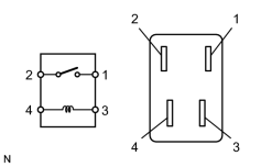
INSPECT RELAY (Marking: IG1 NO. 2) |
|
(a) Remove the IG1 NO. 2 relay from the cowl side junction block LH. (b) Measure the resistance of the relay. Standard resistance:
|
|
| NG |
|
| OK |
|
|
4. |
INSPECT SKID CONTROL ECU CONNECTOR*3 |
(a) Check that each ECU connector is properly installed.
OK:
Each ECU connector is properly installed.
| NG |
|
|
|
5. |
PERFORM ACTIVE TEST BY INTELLIGENT TESTER (ABS WARNING LIGHT) |
(a) Select the ACTIVE TEST, generate a control command, and then check that the ABS warning light operates.
Skid control ECU
|
Item |
Vehicle Condition / Test Details |
Diagnostic Note |
|---|---|---|
|
ABS WARN LIGHT |
Turn ABS warning light ON / OFF |
Observe combination meter |
OK:
ABS warning light turns on or off.
| OK |
|
|
|
6. |
CHECK FOR DTC*4 |
(a) Turn the ignition switch ON.
(b) Check that the ABS warning light illuminates.
(c) Check if the same DTCs are recorded.
Result:
|
Result |
Proceed to |
|---|---|
|
DTC is not output |
A |
|
DTC is output |
B |
| B |
|
|
|
7. |
CHECK WIRE HARNESS (SKID CONTROL ECU ASSEMBLY - COMBINATION METER) |
| NG |
|
| OK |
|

|

|