| Last Modified: 4-30-2014 | 6.6 G | Doc ID: RM000001BV3001X |
| Model Year: 2006 | Model: LX470 | Prod Date Range: [05/2005 - ] |
| Title: 2UZ-FE ENGINE CONTROL SYSTEM: IGNITION RELAY NO. 1: ON-VEHICLE INSPECTION; 2006 MY LX470 [05/2005 - ] | ||
ON-VEHICLE INSPECTION
HINT:
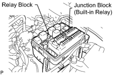
The IG1 NO. 1 relay is built in the engine room junction block. Since the relay is constructed with a relay block that is in the junction block as a unit, it is impossible to disconnecting the wire harness connecting with the relay block.
If the relay has a malfunction, replace it with the junction block assembly wire harness together.
1. CHECK ENGINE ROOM JUNCTION BLOCK (IG1 NO. 1)
|
(a) Disconnect the engine room relay block from the vehicle body. |
|
|
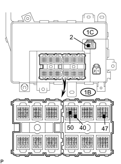
(b) Check the continuity of the relay. OK:
If the continuity is not as specified, replace the engine room junction block. |
|
(c) Install the engine room relay block to the vehicle body.
2. CHECK IG1 NO. 2 RELAY (Marking: IG1 NO. 2)
(a) Remove the relay from the cowl side junction block LH.
|
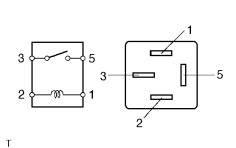
(b) Measure the resistance of the relay. Standard resistance:
If the result is not as specified, replace the relay. |
|
(c) Install the relay.
3. CHECK IG1 NO. 3 RELAY (Marking: IG1 NO. 3)
(a) Remove the relay from the cowl side junction block RH.
|
(b) Measure the resistance of the relay. Standard resistance:
If the result is not as specified, replace the relay. |
|
(c) Install the relay.

|

|