- Exhaust gas sensor
- Harness or connector between exhaust gas sensor and A/C amplifier
- A/C amplifier
| Last Modified: 4-30-2014 | 6.6 C | Doc ID: RM000001CFJ001X |
| Model Year: 2006 | Model: LX470 | Prod Date Range: [05/2005 - ] |
| Title: AIR CONDITIONING: AIR CONDITIONING SYSTEM: 61; Emission Gas NOx Sensor Circuit; 2006 MY LX470 [05/2005 - ] | ||
|
DTC |
61 |
Emission Gas NOx Sensor Circuit |
DESCRIPTION
This sensor detects the exhaust gas (NOx) outside the vehicle and sends signal to the A/C amplifier.
|
DTC No. |
Detection Item |
Trouble Area |
|---|---|---|
|
61 |
Short in exhaust gas sensor circuit |
|
WIRING DIAGRAM
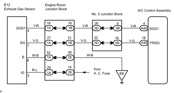
INSPECTION PROCEDURE
PROCEDURE
|
1. |
CHECK AIR CONDITIONING AMPLIFIER |
|
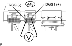
(a) Remove the A/C amplifier with connectors still connected. |
|
(b) Turn the ignition switch ON.
(c) After continuing to turn the ignition switch ON for more than 120 seconds, measure the voltage between terminals DGS1 (A48-4) and FRSG (A48-18) of the A/C amplifier connector at the temperature.
Standard voltage:
1.0 to 4.5 V at 10 to 35°C (50 to 95°F)
HINT:
- When the sensor is exposed to the exhaust gas, the voltage goes down.
- How ever, if DTC 61 is displayed, check and replace the A/C amplifier.
| OK |

|
|

|
2. |
INSPECT EXHAUST GAS SENSOR |
|
(a)
Remove the exhaust gas sensor
|
|
![2006 MY LX470 [05/2005 - ]; AIR CONDITIONING: SMOG VENTILATION SENSOR: REMOVAL](../../../../stylegraphics/info.gif "2006 MY LX470 [05/2005 - ]; AIR CONDITIONING: SMOG VENTILATION SENSOR: REMOVAL")
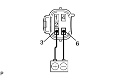
(b) Connect the positive (+) lead from the battery to the terminal 3 (IG) and negative (-) lead to terminal 6 (E).
(c) After keeping to apply battery positive voltage between terminals 3 (IG) and 6 (E) for more than 120 seconds, measure resistance between terminals 1 (SG) and 4 (DGS1).
Standard resistance:
1 to 100 kΩ at 10 to 35°C (50 to 95°F)
HINT:
When the sensor is exposed to the exhaust gas, the voltage goes down.
| NG |
|
|
|
3. |
CHECK WIRE HARNESS (EXHAUST GAS SENSOR - AIR CONDITIONING AMPLIFIER) |
| NG |
|
| OK |
|

|

|