- Steering angle sensor
- Suspension control ECU
- Wire harness
- VGRS ECU
| Last Modified: 4-30-2014 | 6.6 C | Doc ID: RM000001CTN005X |
| Model Year: 2006 | Model: LX470 | Prod Date Range: [05/2005 - ] |
| Title: SUSPENSION CONTROL: ACTIVE HEIGHT CONTROL SUSPENSION: C1777/77,C1781/81; Steering Angle Sensor Circuit; 2006 MY LX470 [05/2005 - ] | ||
|
DTC |
C1777/77 |
Steering Angle Sensor Circuit |
|
DTC |
C1781/81 |
Steering Angle Sensor Circuit |
DESCRIPTION
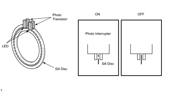
The steering angle sensor is fitted to the turn signal switch assembly and detects the steering rotating direction and angle.
The sensor consists of a slit disc that rotates with the steering wheel as a unit, and a pair of photo interrupters.
Each photo interrupter consists of an LED (Light Emitting Diode) and a photo transistor, which face each other. It converts the change in the light irradiation between the 2 elements to the on/off signals. The slit disc rotates between the LED and the photo transistor of the pair of photo interrupters. As the steering wheel is operated, the slit disc rotates with the wheel as a unit to stop and allow light transmission between the 2 elements. The pair of photo interrupters have phases and the suspension ECU detects the steering direction and angle based on the changes of each output.
When it is judged that the steering wheel's turning angle is large and the speed is greater than a set value, the ECU causes the damping force to increase.
|
DTC No. |
DTC Detection Condition |
Trouble Area |
|---|---|---|
|
C1777/77 |
Steering sensor system signal is abnormal. |
|
|
C1781/81 |
Steering angle 36° or larger signal is not input |
|
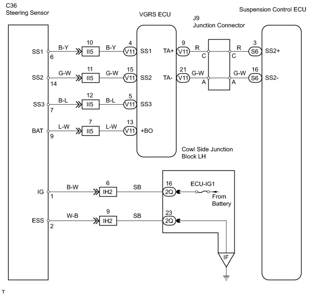
WIRING DIAGRAM
INSPECTION PROCEDURE
PROCEDURE
|
1. |
READ VALUE USING INTELLIGENT TESTER (STEERING ANGLE SENSOR (AHC)) |
(a) Turn the ignition switch LOCK.
(b) Connect the intelligent tester (with CAN VIM) to the DLC3.
(c) Turn the ignition switch ON and push the intelligent tester main switch ON.
(d) Enter the following menus: AHC / DATA LIST.
(e) Select the item "STEERING ANGLE" in the DATA LIST and read the value displayed on the intelligent tester.
(f) Check that the steering wheel turning angle value of the steering angle sensor displayed by the intelligent tester is changing when turning the steering wheel.
OK:
Steering angle turning value is changing.
| NG |

|
| OK |
|
|
2. |
READ VALUE USING INTELLIGENT TESTER (STEERING ANGLE SENSOR (VGRS)) |
(a) Turn the ignition switch LOCK.
(b) Connect the intelligent tester (with CAN VIM) to the DLC3.
(c) Turn the ignition switch ON and push the intelligent tester main switch ON.
(d) Enter the following menus: VGRS / DATA LIST.
(e) Select the items "STEERING POS1" and "STEERING POS2" in the DATA LIST and read the value displayed on the intelligent tester.
(f) Check that the steering wheel turning angle value of the steering angle sensor displayed by the intelligent tester is changing when turning the steering wheel.
OK:
Steering angle turning value is changing.
| NG |
|
|

|
3. |
CHECK WIRE HARNESS (VGRS ECU - SUSPENSION CONTROL ECU) |
(a) Turn the ignition switch LOCK.
(b) Disconnect the suspension control ECU connector.
(c) Disconnect the VGRS ECU connector.
(d) Measure the resistance according to the value(s) in the table below.
Standard resistance:
|
Tester Connection |
Condition |
Specified Condition |
|---|---|---|
|
S6-3 (SS2+) - V11-9 (TA+) |
Always |
Below 1 Ω |
|
S6-16 (SS2-) - V11-21 (TA-) |
Always |
Below 1 Ω |
|
S6-3 (SS2+) - Body ground |
Always |
10 kΩ or higher |
|
S6-16 (SS2-) - Body ground |
Always |
10 kΩ or higher |
| NG |
|
| OK |
|
|
4. |
CHECK WIRE HARNESS (STEERING ANGLE SENSOR POWER SOURCE) |
|
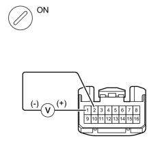
(a)
Remove the steering wheel No. 2 and No. 3 covers, steering wheel pad, and steering wheel column upper and lower covers
|
|
![2006 MY LX470 [05/2005 - ]; STEERING COLUMN: STEERING COLUMN ASSEMBLY: REMOVAL](../../../../stylegraphics/info.gif "2006 MY LX470 [05/2005 - ]; STEERING COLUMN: STEERING COLUMN ASSEMBLY: REMOVAL")
(b) Turn the ignition switch LOCK.
(c) Disconnect the combination switch connector (for steering angle sensor).
(d) Measure the voltage according to the value(s) in the table below.
Standard voltage:
|
Tester Connection |
Condition |
Specified Condition |
|---|---|---|
|
C36-1 (IG) - C36-2 (ESS) |
Ignition switch ON |
9 to 14 V |
| NG |
|
|
|
5. |
CHECK WIRE HARNESS (VGRS ECU - STEERING ANGLE SENSOR) |
(a) Turn the ignition switch LOCK.
(b) Disconnect the VGRS ECU connector.
(c) Disconnect the steering angle sensor connector.
(d) Measure the resistance according to the value(s) in the table below.
Standard resistance:
|
Tester Connection |
Condition |
Specified Condition |
|---|---|---|
|
V11-4 (SS1) - C36-6 (SS1) |
Always |
Below 1 Ω |
|
V11-15 (SS2) - C36-14 (SS2) |
Always |
Below 1 Ω |
|
V11-5 (SS3) - C36-7 (SS3) |
Always |
Below 1 Ω |
|
V11-13 (+BO) - C36-9 (BAT) |
Always |
Below 1 Ω |
|
V11-4 (SS1) - Body ground |
Always |
10 kΩ or higher |
|
V11-15 (SS2) - Body ground |
Always |
10 kΩ or higher |
|
V11-5 (SS3) - Body ground |
Always |
10 kΩ or higher |
|
V11-13 (+BO) - Body ground |
Always |
10 kΩ or higher |
| NG |
|
| OK |
|

|

|