| Last Modified: 4-30-2014 | 6.6 J | Doc ID: RM000001D6V001X |
| Model Year: 2006 | Model: LX470 | Prod Date Range: [05/2005 - ] |
| Title: 2UZ-FE ENGINE CONTROL SYSTEM: SFI SYSTEM: VC Output Circuit; 2006 MY LX470 [05/2005 - ] | ||
|
VC Output Circuit |
DESCRIPTION
The VC voltage (5 V) is generated in the ECM. The voltage is used to supply power to the throttle position sensor, canister pump module, etc.
WIRING DIAGRAM
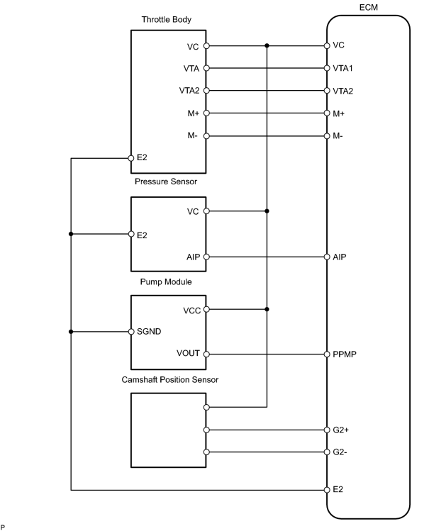
INSPECTION PROCEDURE
PROCEDURE
|
1. |
CHECK MIL |
(a) Check that Malfunction Indicator Lamp (MIL) lights up when turning the ignition switch ON.
OK:
MIL lights up
| OK |

|
|

|
2. |
CHECK CONNECTION BETWEEN INTELLIGENT TESTER AND ECM |
(a) Connect the intelligent tester to the CAN VIM. Then connect the CAN VIM to the DLC3.
(b) Turn the ignition switch ON and intelligent tester ON.
(c) Check the communication between the intelligent tester and ECM.
Result
|
Communication is possible |
A |
|
Communication is not possible |
B |
| A |
|
|
|
3. |
INSPECT ECM |
(a) Turn the ignition switch ON.
|
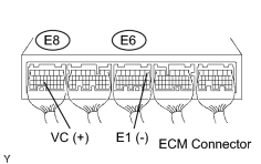
(b) Measure the voltage of the ECM connector. Result: Voltage is not 5 V |
|
|
|
4. |
CHECK MIL (THROTTLE POSITION SENSOR) |
(a) Disconnect the T24 throttle body connector.
(b) Turn the ignition switch ON.
(c) Check the MIL.
Result
|
MIL illuminates |
A |
|
MIL does not illuminate |
B |
| A |
|
|
|
5. |
CHECK MIL (CAMSHAFT POSITION SENSOR) |
(a) Disconnect the C39 camshaft position sensor connector.
(b) Turn the ignition switch ON.
(c) Check the MIL.
Result
|
MIL illuminates |
A |
|
MIL does not illuminate |
B |
| A |
|
|
|
6. |
CHECK MIL (CANISTER PUMP MODULE) |
(a) Remove the spare tire.
|
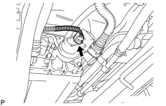
(b) Disconnect the L4 canister pump module connector. |
|
(c) Turn the ignition switch ON.
(d) Check the MIL.
Result
|
MIL illuminates |
A |
|
MIL does not illuminate |
B |
| A |
|
|
|
7. |
CHECK MIL (PRESSURE SENSOR) |
(a)
Remove the intake manifold
![2006 MY LX470 [05/2005 - ]; 2UZ-FE ENGINE MECHANICAL: CYLINDER HEAD: REMOVAL+](../../../../stylegraphics/info.gif "2006 MY LX470 [05/2005 - ]; 2UZ-FE ENGINE MECHANICAL: CYLINDER HEAD: REMOVAL+") .
.
(b) Disconnect the A57 pressure sensor.
(c) Turn the ignition switch ON.
(d) Check the MIL.
Result
|
MIL illuminates |
A |
|
MIL does not illuminate |
B |
| A |
|
|
|
8. |
CHECK HARNESS AND CONNECTOR |
(a) Disconnect the T24 throttle body connector.
(b) Disconnect the C39 camshaft position sensor connector.
(c) Disconnect the L4 canister pump module connector.
(d) Disconnect the A57 pressure sensor.
|
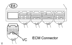
(e) Disconnect the E8 ECM connector. |
|
(f) Measure the resistance of the wire harness side connector.
Standard resistance (check for short):
|
Tester Connection |
Specified Condition |
|---|---|
|
E8-23 (VC) - Body ground |
10 kΩ or higher |
| NG |
|
| OK |
|

|

|