| Last Modified: 4-30-2014 | 6.6 G | Doc ID: RM000001DOH001X |
| Model Year: 2006 | Model: LX470 | Prod Date Range: [05/2005 - ] |
| Title: DOOR LOCK: DOOR CONTROL RECEIVER: ON-VEHICLE INSPECTION; 2006 MY LX470 [05/2005 - ] | ||
ON-VEHICLE INSPECTION
1. INSPECT WIRELESS DOOR LOCK DIAGNOSIS MODE
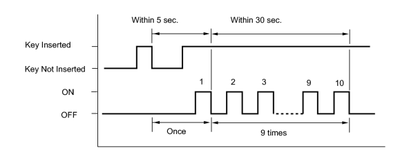
(a) Start the diagnosis mode.
HINT:
This mode is to check the condition of the signal transmission and reception among the transmitter, the receiver and ECU. If all transmitters for a vehicle do not respond, there is a possibility that the receiver or the wire harness is faulty.
(1) Insert the key into the ignition key cylinder.
(2) Remove the key from the ignition key cylinder.
(3) Insert the key into the ignition key cylinder.
(4) Turn the ignition switch ON within 5 seconds.
(5) Repeat turning the ignition switch OFF to ON 9 times within 30 seconds.
(6) Enter the diagnosis mode, and make sure that the taillight lights up.
(b) Finish the Diagnosis Mode.
(1) During the Diagnosis mode, turn the ignition switch from OFF to ON to go back to the normal mode. At this time make sure that the taillight lights up.
(c) Diagnosis Mode Check.
(1) Check how the taillight lights up when pressing each transmitter switch.
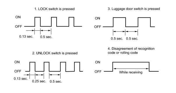
- LOCK switch
- UNLOCK switch
- Luggage door switch
-
Disagreement of recognition code or rolling code
HINT:
If this is detected in the Diagnosis Check, conduct the recognition code registration.
-
No response from the buzzer
HINT:
Conduct the following checks.
- Check the door control transmitter module.
- Check the door control receiver.
2. INSPECT DOOR CONTROL RECEIVER
|
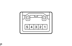
(a) Disconnect the connector from the receiver. |
|
(b) Check the continuity of the wire harness side connector.
OK:
|
Tester Connection |
Specified Condition |
|---|---|
|
1 (E) - Body ground |
Continuity |
If the result is not as specified, repair or replace the harness and connector.
(c) Measure the voltage of the wire harness side connector.
Standard voltage:
|
Tester Connection |
Specified Condition |
|---|---|
|
5 (+B) - Body ground |
4.6 to 5.4 V |
If the result is not as specified, repair or replace the harness and connector.
(d) Reconnect the receiver connector.
(e) Measure the voltage of the connector.
Standard voltage:
|
Tester Connection |
Condition |
Specified Condition |
|---|---|---|
|
2 (RDA) - Body ground |
Ignition switch OFF, all doors closed and transmitter switch not pressed |
11 to 14 V |
|
Ignition switch OFF, all doors closed and transmitter switch pressed |
Pulse generation |
If the result is not as specified, replace the receiver.

|

|