| Last Modified: 4-30-2014 | 6.6 C | Doc ID: RM000001F6D000X |
| Model Year: 2006 | Model: LX470 | Prod Date Range: [05/2005 - ] |
| Title: STEERING COLUMN: VARIABLE GEAR RATIO STEERING SYSTEM: C1568/68; Lock Holder Deviation Detection; 2006 MY LX470 [05/2005 - ] | ||
|
DTC |
C1568/68 |
Lock Holder Deviation Detection |
DESCRIPTION
The VGRS actuator contains a lock mechanism that mechanically locks the DC motor so that the motor will not rotate if a failure occurs or when the engine is not running. The VGRS ECU supplies current to the lock solenoid to release the lock lever for VGRS operation.
When the VGRS ECU detects a malfunction in the lock holder, it turns the warning light on and records the DTC.
|
DTC No. |
DTC Detection Condition |
Trouble Area |
|---|---|---|
|
C1568/68 |
The system detects a malfunction in the actuator lock system. |
VGRS actuator |
INSPECTION PROCEDURE
HINT:
Determine the trouble area by checking the motor revolution angle sensor signal with the intelligent tester.
When not using the intelligent tester, go to *1.
PROCEDURE
|
1. |
OBSERVE DATA FOR MTR REV ANG U, V, W ON INTELLIGENT TESTER |
(a) Connect the intelligent tester (with CAN VIM) to the DLC3.
(b) Turn the ignition switch ON.
NOTICE:
Do not start the engine.
(c) Turn the steering wheel to the right and left.
(d) Using the intelligent tester, display the DATA LIST.
(e) Check the motor revolution angle sensor signal when slowly turning the steering wheel referring to the DATA LIST.
A, B or C as shown below
|
Item |
Proceed to A |
Proceed to B |
Proceed to C |
|||
|---|---|---|---|---|---|---|
|
Turn to left |
Turn to right |
Turn to left |
Turn to right |
Turn to left |
Turn to right |
|
|
MTR REV ANG U |
High |
High |
High |
High |
High |
High |
|
MTR REV ANG V |
Low |
Low |
Low |
Low |
High |
Low |
|
MTR REV ANG W |
Low |
Low |
Low |
High |
Low |
Low |
| NG |

|
| OK |
|
|
2. |
CHECK VOLTAGE MOTOR REVOLUTION ANGLE SENSOR SIGNAL* |
|
(a) Turn the ignition switch ON. NOTICE: Do not start the engine. |
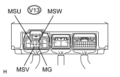
|
(b) Measure the voltage between terminals in the VGRS ECU while slowly turning the steering wheel.
OK:
Proceed to A, B or C as shown below
|
Tester Cnnection |
Proceed to A |
Proceed to B |
Proceed to C |
|||
|---|---|---|---|---|---|---|
|
Turn to left |
Turn to right |
Turn to left |
Turn to right |
Turn to left |
Turn to right |
|
|
V13-4 (MSU) - V13-7 (MG) |
Above 3.5 V |
Above 3.5 V |
Above 3.5 V |
Above 3.5 V |
Above 3.5 V |
Above 3.5 V |
|
V13-8 (MSV) - V1-7 (MG) |
Below 1 V |
Below 1 V |
Below 1 V |
Below 1 V |
Above 3.5 V |
Below 1 V |
|
V13-2 (MSW) - V13-7 (MG) |
Below 1 V |
Below 1 V |
Below 1 V |
Above 3.5 V |
Below 1 V |
Below 1 V |
| NG |
|
| OK |
|

|

|