TERMINAL AND CONNECTOR REPAIR
| Illustration |
Part number |
Part name |
Notes and purpose |
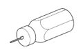 |
09991-00500
09991-00510 |
SST |
To remove the 0.64 connector terminal |
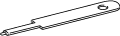 |
09992-01030 |
SST |
To remove the 0.64 II connector terminal |
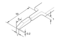 |
- |
Special tool |
To remove the terminal
Refer to the following illustration |
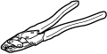 |
09042-2C100 |
SST(Crimping tool) |
To crimp sleeves
(For aluminum wire repair) |
 |
- |
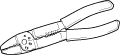
Crimping tool |
To crimp sleeves
(For copper wire repair) |
 |
- |
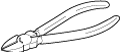
Wire cutters |
To cut wires |
 |
- |
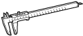
Caliper |
To measure the diameter of a wire and wire strand |
| - |
- |
Dryer or heat gun |
To heat heat shrink sleeves (For aluminum wire repair)
(1000W or more, and the thermal fuse with 190°C or more) |
 |
- |
Wood plate |
To shield heat (For aluminum wire repair)
Size reference (mm): 300 x 100 x 10 |
- Special Tool
-
- REFERENCE:
- To remove the terminal from the connector, please construct and use the special tool or like object shown on the right.
|
Reference: |
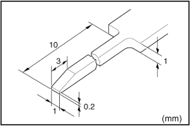 |
The repair parts now in supply are limited to those connectors having common shapes and terminal cavity numbers. Therefore, when there is no available replacement connector of the same shape or terminal cavity number, please use one of the alternative methods described below. Make sure that the terminals are placed in the original order in the connector cavities, if possible, to aid in future diagnosis.
- When a connector with a different number of terminals than the original part is used, select a connector having more terminal ccavities than required, and replace both the male and female connector parts.
EXAMPLE: You need a connector with six terminals, but the only replacement available is a connector with eight terminal cavities. Replace both the male and female connector parts with the eight terminal part, transferring the terminals from the old connectors to the new connectors.
- When several different type terminals are used in one connector, select an appropriate male and female connector part for each terminal type used, and replace both male and female connector parts.
EXAMPLE: You need to replace a connector that has two different types of terminals in one connector. Replace the original connector with two new connectors, one connector for one type of terminal, another connector for the other type of terminal.
- When a different shape of connector is used, first select from available parts a connector with the appropriate number of terminal cavities, and one that uses terminals of the same size as, or larger than, the terminal size in the vehicle. The wire lead on the replacement terminal must also be the same size as, or larger than, the nominal size of the wire in the vehicle. ("Nominal" size may be found by looking at the illustrations in the section F or by direct measurement across the diameter of the insulation). Replace all existing terminals with the new terminals, then insert the terminals into the new connector.
EXAMPLE: You need to replace a connector that is round and has six terminal cavities. The only round replacement connector has three terminal cavities. You would select a replacement connector that has six or more terminal cavities and is not round, then select terminals that will fit the new connector. Replace the existing terminals, then insert them into the new connector and join the connector together.
These steps must be followed when replacing a terminal.
If the wire harness is protected with CFWs, refer to [Extra].
| Step 1. Identify the connector and the terminal type. |

| Step 2. Disconnect the terminal from the connector. |
| Step 3. Replace the terminal. |
| Step 4. Install the terminal into the connector. |
| Extra. Special handling for the wires that are protected with CFWs. |
| Step 1. Identify the connector and the terminal type. |
1. Connector Body
- Identify the part number of the corresponding terminal with wire according to the above-mentioned 1.
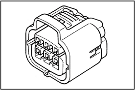
- Identify the part number of the connector body by picking out the correct one from the illustrations according to the number of terminals and the shape.
- REFERENCE:
-
- If you can find no connector which matches the type you require, pick out male and female connector bodies as a set which have more terminals than you require.
For the combined terminal type connector body, pick out and appropriate connector body for each terminal being used.
-
- Example:
- When two types of terminal are used in one connector body, pick out a male and female for two different connector bodies.
|
 |
-
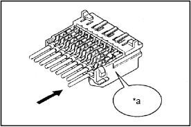
- The part number has been stamped on the back of the connector body. (This will continue to be done to new types of connector.)
|
Example: |
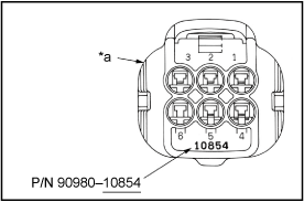 |
| *a |
Back of the Connector Body |
|
2. Terminal with Wire
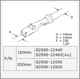
- Identify the part number of the terminal with wire by picking out the corresponding illustration from the pictures provided on the following charts.
-
- REFERENCE:
- In some of the illustrations, there are two part numbers for the same illustration of terminal with wire, because although the shapes of the terminals are completely the same, there is a difference in with /without gold-plating (gilded).
- NOTICE:
-
- When the terminal used is gold plated, be sure to replace it with a gold plated terminal when marking repairs.
- Do not use male and female terminals which are made of different materials from each other.
|
 |
- REFERENCE:
-
-
To calculate the "Nominal Size" of the wire.
| Nominal size |
| = |
3.14 x (Diameter of stripped wire harness)2 |
| 4 |
|
Nominal Size of Wire |
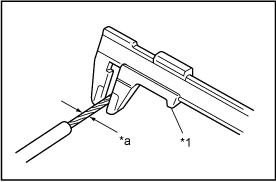 |
| *1 |
Calipers |
| *a |
Rubber Plug |
|
3. Copper wire sleeves
- When connecting two wires using a sleeve, select the sleeve according to the following table.
|
 |
Small (Red) |
 |
Medium (Blue) |
 |
Large (Yellow) |
|
When size is based on the outside diameter of the wire.
-
| Wire Outside Diameter |
Sleeve Size (Color) |
| 0.2-1.0 mm |
Small(Red) |
| 1.0-2.0 mm |
Medium(Blue) |
| 3.0-5.0 mm |
Large(Yellow) |
|
Wire Outside Diameter |
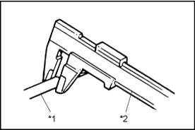 |
| *1 |
Insulation |
| *2 |
Calipers |
|
When size is based on the nominal size of the wire.
- Sleeve size
-
| S |
: |
Small (Red) |
| M |
: |
Medium (Blue) |
| L |
: |
Large (Yellow) |
| * |
0.13 |
0.22 |
0.3 |
0.5 |
0.85 |
1.25 |
2 |
3 |
5 |
| 0.13 |
- |
- |
- |
S |
- |
- |
- |
- |
- |
| 0.22 |
- |
- |
- |
S |
- |
- |
- |
- |
- |
| 0.3 |
- |
- |
S |
M |
M |
M |
M |
L |
L |
| 0.5 |
S |
S |
M |
M |
M |
M |
M |
L |
L |
| 0.85 |
- |
- |
M |
M |
M |
M |
L |
L |
L |
| 1.25 |
- |
- |
M |
M |
M |
M |
L |
L |
L |
| 2 |
- |
- |
M |
M |
L |
L |
L |
L |
- |
| 3 |
- |
- |
L |
L |
L |
L |
L |
L |
- |
| 5 |
- |
- |
L |
L |
L |
L |
- |
- |
- |
*Nominal size of the wire
4. Aluminum wire sleeves
- When two wires are joined using a sleeve, select the appropriate sleeve by referring to the table shown on the right.
Nominal wire size and sleeve size
-
Nominal wire
size |
Sleeve size
(Color) |
| 0.75-1.0 sq |
S (Silver) |
| 1.25-2.5 sq |
M (Silver) |
|
 |
S (Silver) |
 |
M (Silver) |
|
| Step 2. Disconnect the Terminal from the Connector. |
1. Disconnect Connector
- To pull apart the connectors, pull on the connector itself, not the wire harness.
- HINT:
- Check to see what kind of connector you are disconnecting before pulling apart.
Press down type is mainly used.
|
Example: |
|
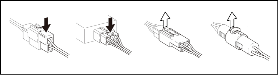 |
|
 |
Press Down |
 |
Pull Up |
|
2. Prepare the Special Tool
- HINT:
- To remove the terminal from the connector, please construct and use the special tool or like object shown on the right.
|
Reference: |
|
Reference:(for 1.0III KITCUT Type) |
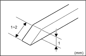 |
3. Disengage the double locking device or terminal retainer.
- Locking device must be disengaged before the terminal locking clip can be released and the terminal removed from the connector.
- Use a special tool or the terminal pick to unlock the double locking device.
-
- NOTICE:
- Do not remove the terminal retainer from connector body.
|
Example: |
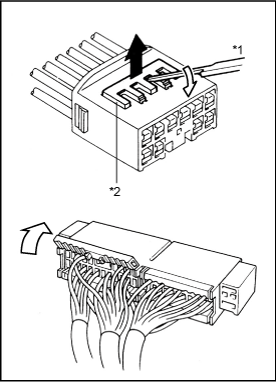 |
|
Pull Up |
| *1 |
Tool |
| *2 |
Terminal Retainer |
|
- Type A (For 0.64II, 0.64III, 1.0II, 1.8, 2.3II, 4.8 and 8.0 of Non-Waterproof Type Connector)
-
| (1) |
Using the special tool, raise the retainer up to the temporary lock position. |
- HINT:
- The needle insertion position varies according to the connector's shape (number of terminals, etc.), so check the position before inserting it.
|
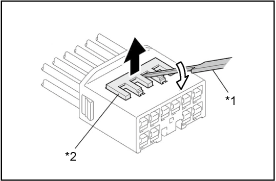 |
| *1 |
Special Tool |
| *2 |
Terminal Retainer |
|
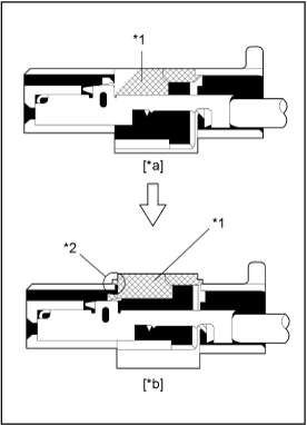 |
| *1 |
Terminal Retainer |
| *2 |
Stopper |
| *a |
Retainer at Full Lock Position |
| *b |
Retainer at Temporary Lock Position |
|
|
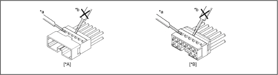 |
|
| *A |
Male |
*B |
Female |
| *a |
Good |
*b |
Bad |
|
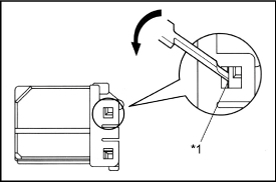
- Type B (For 1.8, 1.0 and TLC of Non-Waterproof Type Connector)
-
| (1) |
Press the special tool at a 45° angle into the locking lug access hole as shown.
Raise the double locking device up as far as possible.
|
|
 |
|
|
-
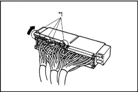
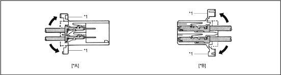
| (2) |
The lock is released and lever is lifted up. |
-
- NOTICE:
- TLC housing is not be reusable. Please replace it with the new one after replacement of the terminal.
|
 |
|
|
|
 |
|
|
Open |
- |
|
| *A |
Male |
*B |
Female |
| *1 |
Double Locking Device |
- |
|
|
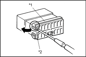
- Type C (For TNS, FTC Type Connector)
-
| (1) |
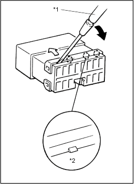
Widen the side lock part of the retainer from side to side using the special tool. |
|
 |
|
|
-
| (2) |
Inset the special tool into the chink between the retainer and the terminal itself. Then pry it to the direction of the arrow shown in the illustration and push the retainer up to release the lock. |
- NOTICE:
- Do not insert the special tool too much. It may cause damage on the fit section of the terminal and the wire harness.
- TNS housing is not reusable. Please replace it with the new one after replacement of the terminal.
|
 |
|
|
- Type D (For 1.3 of Non-Waterproof Type Connector)
- [Case 1]
| (1) |
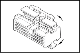
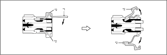
Use the special tool to unlock the double locking device. |
|
 |
|
 |
|
| *1 |
Special Tool |
*2 |
Double Locking Device |
|
- [Case 2]
| (1) |
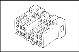
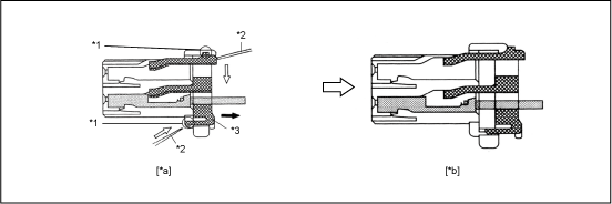
Using the special tool, push the terminal retainer locking lug (clip) and pull the terminal retainer up to the temporary lock position. |
|
 |
|
|
 |
|
| *1 |
Locking Lug |
*2 |
Spacial Tool |
| *3 |
Terminal Retainer |
- |
|
| *a |
Retainer at Full Lock Position |
*b |
Retainer at Temporary Lock Position |
|
- [Case 3]
| (1) |
Using the special tool, raise the retainer up to the temporary lock position. |
|
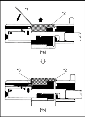 |
| *1 |
Special Tool |
| *2 |
Terminal Retainer |
| *3 |
Stopper |
| *a |
Retainer at Full Lock Position |
| *b |
Retainer at Temporary Lock Position |
|
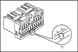
- [Case 4]
|
 |
|
|
-
| (1) |
Insert the special tool into the service hole and move it to the direction of the arrow to release the lock on the side A. |
| (2) |
Push the lock on the side B up by the special tool and release the lock. Then pull the retainer forward. |
|
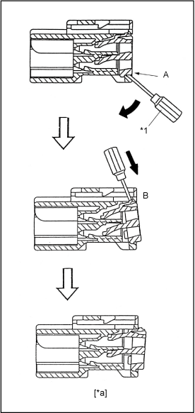 |
| *1 |
Special tool |
| *a |
Appearance when the double locking is released |
|
- Type E (For 0.64, 1.8, 2.3, 2.3II, 4.8, 6.3 and 8.0 of Waterproof Type Connector)
-
- HINT:
- Terminal retainer color is different according to connector body.
- Example:
-
| Terminal Retainer |
: |
Connector body |
| Black or White |
: |
Gray |
| Black or White |
: |
Dark Gray |
| Gray or White |
: |
Black |
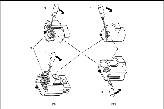
- [Case 1]
- Type where terminal retainer is pulled up to the temporary lock position (Pull Type).
|
 |
|
| *A |
Female |
*B |
Male |
| *1 |
Special tool |
*2 |
Terminal Retainer |
| *3 |
Access Hole |
- |
|
|
-
| (1) |
Insert the special tool into the terminal retainer access hole ( Mark) and pull the terminal retainer up to the temporary lock position. Mark) and pull the terminal retainer up to the temporary lock position. |
-
- HINT:
- The needle insertion position varies according to the connector's shape (Number of terminals etc.), so check the position before inserting it.
|
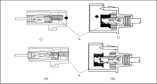 |
|
| *A |
Male |
*B |
Female |
| *a |
Terminal Retainer at Full Lock Position |
*b |
Temporary Lock Position |
|
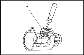
- HINT:
- In some cases insert the special tool from the access hole on the flank of the housing.
|
 |
|
|
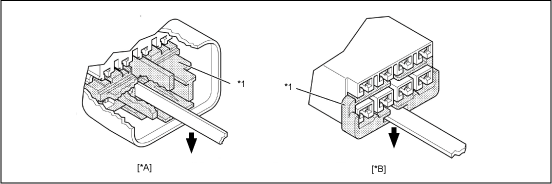
- [Case 2]
- Type which cannot be pulled as far as Power Lock
- HINT:
- There are few cases of this type of connector
|
 |
|
|
Press Down |
- |
|
| *A |
Male |
*B |
Female |
| *1 |
Terminal Retainer |
- |
|
|
-
| (1) |
Insert the tool straight into the access hole of terminal retainer as shown.
Push the terminal retainer down to the temporary lock position. |
|
Example: |
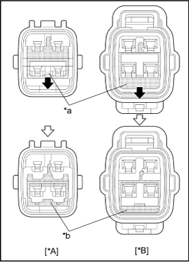 |
| *A |
Male |
| *B |
Female |
| *a |
Retainer at Full Lock Position |
| *b |
Retainer at Temporary Lock Position |
|
- Type F (For C-Type Connector)
-
| (1) |
Insert the special tool into the service hole. |
|
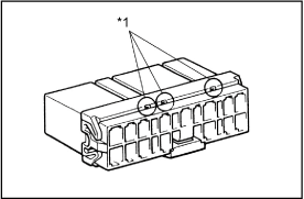 |
|
|
-
| (2) |
Move the special tool to the direction of the arrow and release the lock. |
- HINT:
- Lift the retainer up after moving it to the direction of the thin arrow shown in the illustration.
| (3) |
Pull the retainer forward by hand and remove the retainer from the housing. |
|
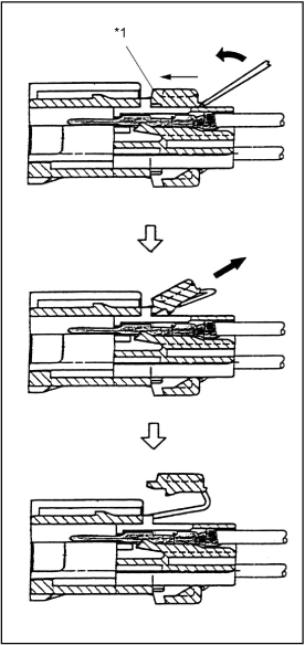 |
|
|
- Type G
-
| (1) |
Insert the special tool into the position shown in the illustration. Pry it to the direction of the arrow and push the lock up to release it. |
|
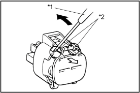 |
|
|
- Type H (For 1.0II Type Connector)
-
| (1) |
Move the special tool into the notch of the retainer to the direction of the arrow with the edge of the housing as the fulcrum. Then the pull the retainer out. |
-
- NOTICE:
- Do not insert the special tool into areas except notches. (This may damage the seal ring that is attached behind the retainer.)
-
| (2) |
As same as the procedure (1), pull the retainer straight out using hand after releasing the lock on the other side. |
|
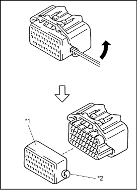 |
| *1 |
Retainer (Yellow) |
| *2 |
Notch |
|
- NOTICE:
-
- Do not remove the seal rubber when pulling the terminal out.
- If the seal rubber is peeled off when puling the terminal out, press it down to stick it to the original condition.
- Be sure and not fit the connector when the retainer is not installed.
|
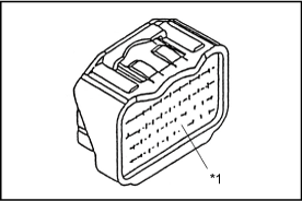 |
|
|
- Type I (For SFPC Type Connector)
-
| (1) |
Open the cover (white) |
|
Condition of cover opening |
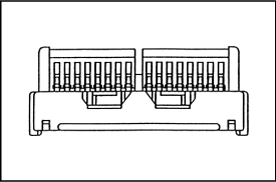 |
-
| (2) |
Remove the side lock of the retainer. (One side) |
| (3) |
Remove the center lock of the housing. |
| (4) |
Remove the side lock of the retainer. (The other side) |
- NOTICE:
- Following the above order is not required.
- No center lock on the housing with ten poles.
|
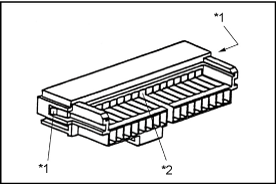 |
| *1 |
Side Lock |
| *2 |
Center Lock |
|
-
| (5) |
Move the retainer until it becomes the initial condition. |
|
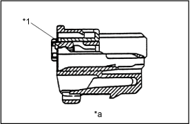 |
| *1 |
Retainer |
| *a |
Initial condition |
|
- Type J
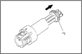
- [Male]
-
| (1) |
Remove the rubber plug. |
|
 |
|
|
-
| (2) |
Push the lock of the inner using the special tool. |
| (3) |
Pull the wire to the direction of the arrow pushing the lock up and remove the inner from the outer. |
|
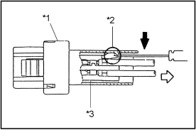 |
| *1 |
Outer |
| *2 |
Lock |
| *3 |
Inner |
|
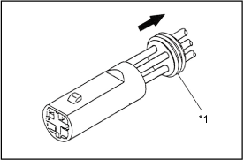
- [Female]
-
| (1) |
Remove the rubber plug. |
|
 |
|
|
-
| (2) |
Insert the special tool into the outer shown in the illustration. Then push the area A of the inner and remove the inner from the outer. |
|
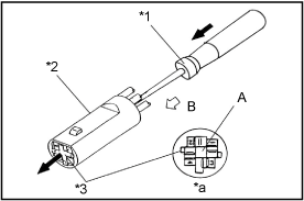 |
| *1 |
Special tool |
| *2 |
Outer |
| *3 |
Inner |
| *a |
Illustration from side B |
|
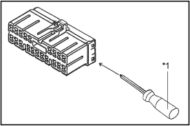
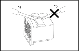
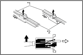
- Type K (For Insulation Displacement Connector)
-
| (1) |
Separate Connector
Using a special tool, release the lock and separate the connector into 2. |
-
- NOTICE:
- Do not apply too muck force to the lock arm.
|
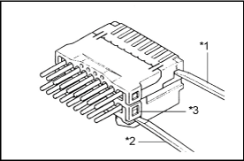 |
| *1 |
Special Tool |
| *2 |
Special Tool |
| *3 |
Lock |
|
-
| (2) |
w/ Cover : Open Connector Cover
Using a special tool, release the lock and open the cover. |
-
- NOTICE:
- Do not apply too much force to the lock arm.
|
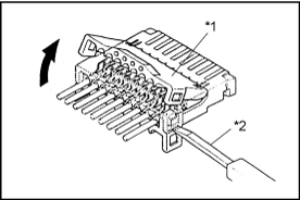 |
|
|
- Type L (For 0.64 Type Connector)
-
| (1) |
Using the special tool, raise the retainer up to the temporary lock position. |
-
- HINT:
- The needle insertion position varies according to the connector's shape (number of terminals, etc.), so check the position before inserting it.
|
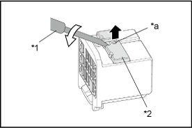 |
|
Pull Up |
| *1 |
Special Tool |
| *2 |
Terminal Retainer |
| *a |
Special Tool Insert Mark |
|
|
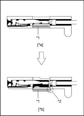 |
| *1 |
Terminal Retainer |
| *2 |
Stopper |
| *a |
Retainer at Full Lock Position |
| *b |
Retainer at Temporary Lock Position |
|
- Type M (For 0.64 of Insulation Displacement Connector (IDC) Type)
-
| (1) |
Remove the Lower Housing
Using a special tool, release the lock and remove the lower housing. |
- NOTICE:
- Do not apply too much force to the lock arm.
- Mark the upper housing and lower housing to prevent mistakes when putting them together.
|
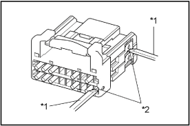 |
|
|
-
| (2) |
Remove the Upper Housing
Using a special tool, release the lock and remove the upper housing from the lock housing. |
- NOTICE:
- Do not apply too much force to the lock arm.
- Mark the upper housing and lower housing to prevent mistakes when putting them together.
|
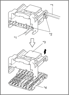 |
| *1 |
Special Tool |
| *2 |
Lock |
| *3 |
Lock Housing |
| *4 |
Upper Housign |
|
- Type N (For 0.64II Type Connector)
-
| (1) |
Insert the tool into the insertion position near the tool mark and raise the terminal retainer up to the temporary lock position using the tool. |
|
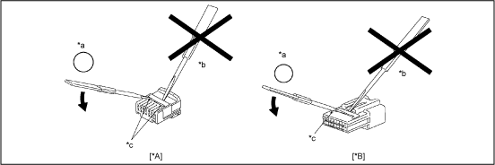 |
|
| *A |
Female |
*B |
Male |
| *a |
Good |
*b |
Bad |
| *c |
Tool Mark |
- |
|
|
- Disengagement order
- NOTICE:
- Use a precision screwdriver (1.2mm) or special tool when disengaging the terminal retainer.
- Do not insert the tool into any position other than the tool insertion positions. After disengaging the terminal retainer, be sure to check that the terminal retainer has not been deformed. If it has been deformed, replace it with a new one.
- Some connectors have 2 or more tool insertion positions. When disengaging the terminal retainer from these types of connectors, follow the disengagement order shown in the illustration on the right.
|
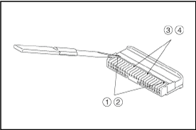 |
- Type O (For 1.0III of KITCUT Type Connector)
-
| (1) |
Insert a jig horizontally into the jig insertion hole. |
| (2) |
Push the jig in until it stops. |
|
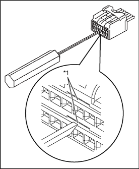 |
|
|
-
| (3) |
Pull out the wire in the direction indicated by the arrow and remove the housing. |
|
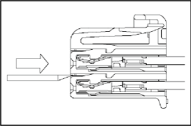 |
4. Disconnect Terminal from Connector
- Push the terminal gently into the connector and hold it in this position.
|
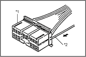 |
| *1 |
Connector |
| *2 |
Wire Harness |
|
- Insert the special tool into the connector in the direction shown in the chart.
- Move the locking clip to the unlock position and hold it there.
- NOTE:
- Do not apply excessive force to the terminal.
Do not pry on the terminal with the special tool.
Carefully withdraw the terminal from the connector by pulling the lead toward the rear of the connector.
- NOTE:
- Do not use too much force. If the terminal does not come out easily, repeat steps (a) through (e).
|
Waterproof Type |
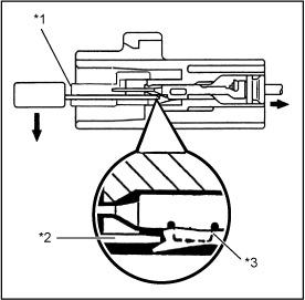 |
| *1 |
Terminal Retainer |
| *2 |
Special Tool |
| *3 |
Locking Clip |
|
|
Non-Waterproof Type:(4.8) |
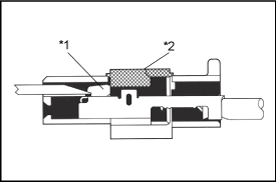 |
| *1 |
Locking Clip |
| *2 |
Terminal Retainer |
|
- Insert the SST into the connector in the direction shown in the chart.
- Insert the SST fully to the tool hole, and push the terminal lance.
- NOTICE:
-
- The terminal has a lance shape, therefore, the housing may be damaged and the terminal may get stuck if forcibly pried by wires etc.
- Insert the SST so that the stopper portion surface is facing up.
- Carefully withdraw the terminal from the connector by pulling the lead toward the rear of the connector.
-
- NOTICE:
- Removal of the terminal from housing cavity will cause damage to the wire seal section, deteriorating waterproofing performance. Replace the connector with a new one.
|
0.64 Type |
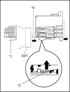 |
| *1 |
Tool Hole |
| *2 |
Terminal Lance |
| *a |
Stopper Portion |
|
-
- NOTICE:
- Do not insert the special tool into the female terminal box. If you do so, replace the terminal with the new one whether the terminal is broken or not.
|
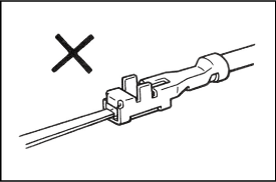 |
-
- NOTICE:
- As for Non-waterproof type TLC housing, insert the special tool into the housing from wire harness side.
|
Non-Waterproof type (TLC housing) |
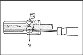 |
| *a |
Insert the tool from wire harness side |
|
Insulation Displacement Connector Type
Using a special tool, push the terminal lance from the tool hole.
Carefully withdraw the terminal from the connector by pulling the lead toward the rear of the connector.
- NOTICE:
-
- Do not use too much force. If the terminal does not come out easily, repeat step (a).
- Always change the wire with the repair wire, in accordance with step 3.
|
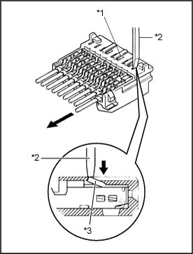 |
| *1 |
Tool Hole |
| *2 |
Special Tool |
| *3 |
Terminal Lance |
|
|
0.64 Type |
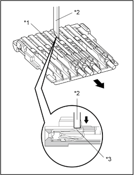 |
| *1 |
Tool Hole |
| *2 |
Special Tool |
| *3 |
Terminal Lance |
|
1.0III of KITCUT Type Connector
Remove Female Terminal
-
| (1) |
Insert the jig tip at an angle, as shown in the illustration on the right. |
| (2) |
Move the jig in the direction indicated by the arrow to push and release the primary lock. |
|
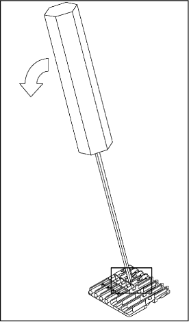 |
-
| (3) |
Pull out the terminal in the direction indicated by the arrow and detach it. |
- NOTICE:
-
- Do not remove and reinstall the same terminal more than 3 times.
- If the terminal is deformed at all, dispose of it.
- Do not apply too much force when releasing the primary lock.
- Do not apply too much force when pulling out the terminal. If the terminal does not come out easily, repeat steps (1) to (3).
|
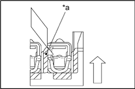 |
| *a |
Pull Out Terminal While Pushing |
|
Remove the insulation displacement female terminal
- NOTICE:
- Do not repair the insulation displacement female terminal.
- Always replace the part with a new one if any terminals are removed.
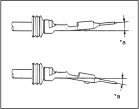
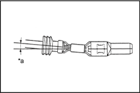
5. Inspect the terminal and the connector for damage.
- NOTE:
-
- The locking clip is easily damaged.
- Do not reuse the damaged part.
|
Terminal Bending in Vertical Direction |
 |
|
|
Terminal Bending in Horizontal Direction |
 |
|
|
| Step 3. Replace the terminal. |
Copper wires
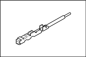
1. Select the appropriate repair wire terminal
- Select the correct replacement terminal with lead, from the supply parts.
|
 |
2. Replace the wire terminal.
- Use the new wire lead as a guide for proper length.
-
- REFERENCE:
- If the length of wire removed is not approximately the same length as the new piece, the following problems may develop:
- Too short -- tension on the terminal, splice, or the connector, causing and open circuit.
- Too long -- excessive wire near the connector, may get pinched or abraded, causing a short circuit.
|
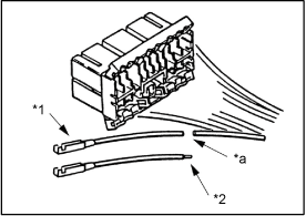 |
| *1 |
Existing terminal |
| *2 |
Repair wires |
| *a |
Cut |
|
-
- REFERENCE:
- When connecting a wire harness at there or more spots to the same connector, cut the wire harness as shown on the right.
|
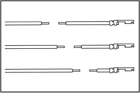 |
3. Remove the sheaths from the existing wire and the repair terminal wire.
- Start stripping at least 8 mm to 11 mm away from the end of the existing harness at vehicle side and also from the end of the repair wire.
-
|
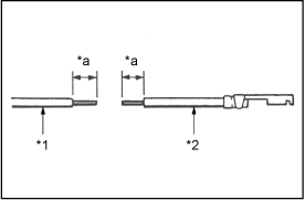 |
| *1 |
Existing Harness |
| *2 |
Repair Wires |
| *a |
8~11 (mm) |
|
-
- NOTICE:
- Do not damage or cut the wire strand. After the sheath is removed, visually check the wire. If any damage is found, do the sheath removal again.
|
Good Example: |
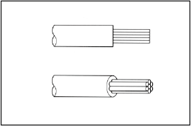 |
Bad Example: |
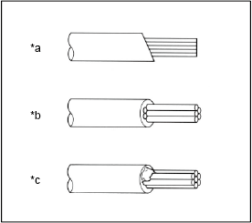 |
| *a |
Wire insulation is Stripped at Slant |
| *b |
Wire Lead is Cut |
| *c |
Insulation Remains on the Lead |
|
4. Select Correct Size of Sleeve from the Supply Parts.
- Using a caliper, measure the outer diameter of the wire or the diameter of the wire strand.
-
- When the sleeve size is determined according to the wire outer diameter:
Measure the outer diameter of the wire using a caliper.
|
Wire Harness Outside Diameter |
|
| *1 |
Insulation |
| *2 |
Calipers |
|
-
- When the sleeve size is determined according to the nominal diameter of the wire strand:
Measure the diameter of the wire strand using a caliper.
-
- REFERENCE:
- To calculate the "nominal size" of wire
| Nominal size |
| = |
3.14x(Diameter of wire lead)2 |
| 4 |
|
Nominal Size of Wire |
|
| *1 |
Calipers |
| *a |
Wire Lead Diameter |
|
- Use the table to determine proper sleeve size
-
| Sleeve size |
Part Number |
Nominal size of wire
(Outside Diameter of wire) |
| Small |
82999-12010 |
0.3 or less
(1.0 - 0.2 mm) |
| Medium |
82999-12020 |
0.5 - 1.25
(2.0 - 1.0 mm) |
| Large |
82999-12030 |
2 or more
(5.0 - 3.0 mm) |
|
|
Small (Red) |
|
Medium (Blue) |
|
Large (Yellow) |
|
5. Join the strands of the existing wire and new terminal wire
-
- NOTICE:
- If unauthorized work procedures, crimping tools or sleeves are used in copper wire repair, an improper wire connection may occur.
- When nominal size is 0.3 or more
Overlap the two stripped wire ends inside the sleeve as illustrated on the right.
|
Good Example: |
 |
| *1 |
Sleeve (Blue) |
| *a |
Two Stripped Wires |
| *b |
Pressure-Contact Section |
|
Bad Example: |
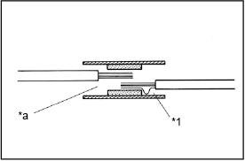 |
| *1 |
Wire Bend |
| *a |
Wire in Short Position |
|
-
- REFERENCE:
- You might find it easier if you use a miniature special tool as a guide as you insert wires into the sleeve.
|
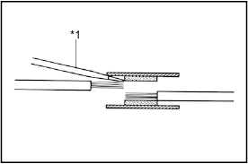 |
|
|
- When nominal size is less than 0.3.
-
- Two stripped wire ends are arranged for the same as illustrated on the right.
|
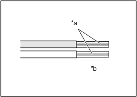 |
| *a |
Two Stripped Wires |
| *b |
It arranges it for the same |
|
-
- Twist the two stripped wire ends together.
|
Good Example: |
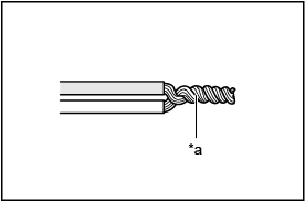 |
| *a |
Wires are Twisted uniformly together |
|
Bad Example: |
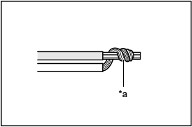 |
| *a |
The thin wire is twisted around the thick wire |
|
-
- Insert the twisted wire ends into the sleeve.
|
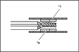 |
| *1 |
Sleeve (Red) |
| *a |
Pressure-Contact Section |
|
- The crimp portion of the copper wire crimping tool has the color marks on it. Place the sleeve in the correct portion of the color mark that corresponds to the color of the sleeve.
|
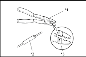 |
| *1 |
Crimping Tool |
| *2 |
Sleeve |
| *3 |
Color Marks |
|
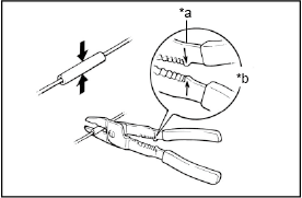
- With the center of the sleeve correctly placed between the crimping jaws, squeeze the crimping tool until either end comes into contact at the section marked by "CLOSE HERE".
-
- REFERENCE:
- Check to see that the sleeve and wires are still in the correct position before closing the crimping tool ends with steady pressure.
|
 |
|
|
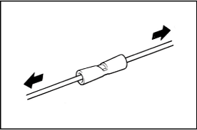
- Pull the joined wires to either end. Make sure that they are joined firmly by the sleeve.
-
- NOTICE:
- If the connected wire(s) is pulled out from the crimped sleeve or crimping has failed, replace the sleeve with a new one and then crimp again.
|
 |
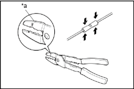
- Crimp both ends of the sleeve with the crimping tool at the "INS" position.
|
 |
|
|
6. Waterproof and insulate the joint area
|
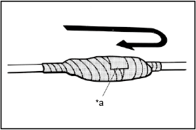
Wrap silicon tape around the joins to protect them from moisture.
-
- REFERENCE:
- This job is required in repairs of the engine compartment, under the floor and other moisture entry positions.
|
 |
|
|
- REFERENCE:
- Before starting the operation, thoroughly wipe dirt and grease off the sections to be joined.
- If the adhesive surfaces of two tapes come in contact they will stick together and will not come apart, so do not remove the backing film except when using the tape.
- Do not let oil and dust, etc. get on the tape surface.
|
 |
|
|
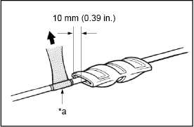
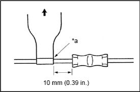
- Ready about 100 mm (3.94 in.) of silicon tape (Part No. 08231-00045) and peel off the film.
- Stretch the silicon tape until its width is reduced by half.
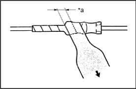
- About 10 mm (0.39 in.) from the end of the sleeve, wrap the silicon tape around the sleeve three or more times while stretching the tape.
- Wrap the remaining part of the sleeve with half of the tape overlapping at each turn.
|
 |
|
|
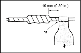
- Firmly wrap the tape two times or more about 10 mm (0.39 in.) from the other end of the sleeve, then wrap the tape back towards the start again and firmly finish winding the tape around the center of the sleeve.
|
 |
|
|
Aluminum wires
1. Select the appropriate repair wire terminal
- Select the correct replacement terminal with lead, from the supply parts.
|
|
2. Replace the wire terminal.
- Use the new wire lead as a guide for proper length.
-
- REFERENCE:
- If the length of wire removed is not approximately the same length as the new piece, the following problems may develop:
- Too short -- tension on the terminal, splice, or the connector, causing and open circuit.
- Too long -- excessive wire near the connector, may get pinched or abraded, causing a short circuit.
|
|
| *1 |
Existing terminal |
| *2 |
Repair wires |
| *a |
Cut |
|
-
- REFERENCE:
- When connecting a wire harness at there or more spots to the same connector, cut the wire harness as shown on the right.
|
|
3. Remove the sheaths from the existing wire and the repair terminal wire.
- Start stripping at least 8 mm to 11 mm away from the end of the existing harness at vehicle side and also from the end of the repair wire.
|
|
| *1 |
Existing Harness |
| *2 |
Repair Wires |
| *a |
8~11 (mm) |
|
-
- NOTICE:
- Do not damage or cut the wire strand. After the sheath is removed, visually check the wire. If any damage is found, do the sheath removal again.
|
Good Example: |
|
Bad Example: |
|
| *a |
Wire insulation Stripped at a Slant |
| *b |
Wire Lead is Cut |
| *c |
Insulation Remains on the Lead |
|
4. Select Correct Size of Sleeve from the Supply Parts.
- Using a caliper, measure the outer diameter of the wire or the diameter of the wire strand.
-
- REFERENCE:
- To calculate the "nominal size" of wire
| Nominal size |
| = |
3.14x(Diameter of wire lead)2 |
| 4 |
|
Nominal Size of Wire |
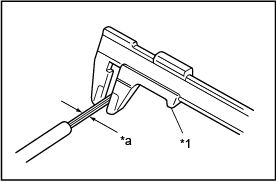 |
| *1 |
Calipers |
| *a |
Wire Lead Diameter |
|
- Use the table to determine proper sleeve size
-
| Sleeve size |
Part number |
Nominal wire size(mm2) |
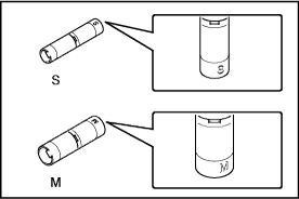
| S |
82999-52010 |
0.5-1.0 |
| M |
82999-52020 |
1.25-2.5 |
|
 |
5. Join the strands of the existing wire and new terminal wire
-
- NOTICE:
- If unauthorized work procedures, crimping tools or sleeves are used in aluminum wires repair, an improper wire connection may occur.
- Using the table shown below, confirm the appropriate sleeve size and crimp size.
-
| Sleeve size |
Crimp size |
Crimp mark |
| S |
1.25 |
1 |
| M |
2 |
2 |
| Part name |
Part number |
| SST(Crimping tool) |
09042-2C100 |
|
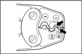 |
- Squeeze the tool handles to disengage the ratchet.
- Place the sleeve in the crimping area of the tool, and hold the tool handles to hold the sleeve.
-
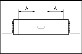
- REFERENCE:
- Hold the area A shown in the illustration.
|
 |
-
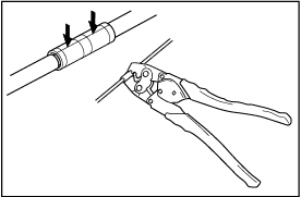
- NOTICE:
- Ensure that the protrusion of the tool's crimping portion will come into contact with the seam of the sleeve.
Insert the wire into the sleeve as far as it can go.
Squeeze the tool handles until the ratchet disengages again.
|
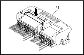
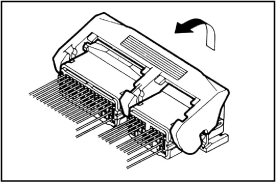
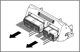
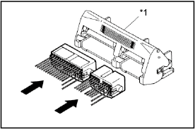
 |
- Check that the crimp mark is correct.
|
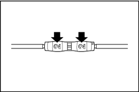 |
- Pull the connected wires to check that they have been connected securely.
-
- NOTICE:
- If the connected wire(s) is pulled out from the crimped sleeve or crimping has failed, replace the sleeve with a new one and then crimp again.
|
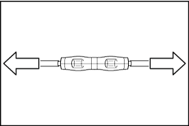 |
6. Waterproof and insulate the joint area
- Cover the joints with heat shrink sleeves, and position the joints at the center of the sleeves.
-
| Part name |
Part number |
| Heat shrink sleeve |
82999-30010 |
|
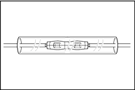 |
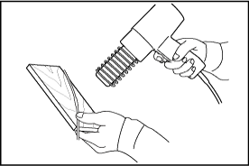
- Using a dryer or heat gun, apply hot air to a heat shrink sleeve for about 10 seconds.
- REFERENCE:
- When a heat gun is used, keep it 100 to 200mm away from the shrink sleeve.
- When a dryer is used, keep it about 10mm away from the shrink sleeve.
|
When a drier is used |
 |
When a heat gun is used |
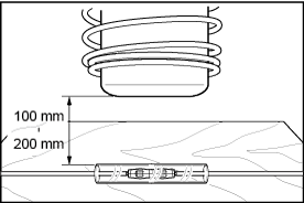 |
- NOTICE:
- Use a wood plate to prevent hot air from being applied to other wires.
- Be careful when using a dryer or heat gun. Otherwise burn injuries may result.
|
 |
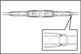
- Turn off the dryer or heat gun, and check if a resin substance has come out of the gap between the shrink sleeve and wire at each sleeve end. Repeat step (b) described above until resin substances come out.
|
 |
| Step 4. Install the terminal into the connector. |
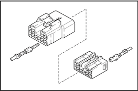
- HINT:
- Make sure the terminal is positioned correctly.
- Insert the terminal until the locking clip locks firmly.
- Insert the terminal with terminal retainer in the temporary lock position, if equipped.
|
 |
-
- NOTE:
- If reusing a terminal, check that the locking clip is still in good condition and in the proper position.
-
- If it is on the terminal and not in the proper position, use the special tool to gently bend the locking clip back to the original shape.
- Check that the other parts of the terminal are in their original shape.
|
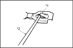 |
| *1 |
Locking clip |
| *2 |
Special Tool |
|
-
- NOTICE:
- Do not readjust or reuse the terminal lance of the insulation displacement connector type terminal. Always change the wire with the repair wire.
|
Insulation Displacement Connector |
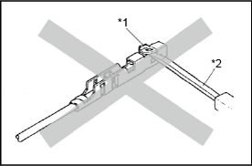 |
| *1 |
Terminal Lance |
| *2 |
Special Tool |
|
-
- NOTICE:
- As for 0.64 type terminal, do not adjust the terminal lance with the special tool.
|
0.64 Type |
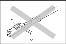 |
| *1 |
Terminal Lance |
| *2 |
Special Tool |
|
Splash Proof Type Connector
- NOTICE:
- Removal of the terminal from housing cavity will cause damage to rubber plug material (the wire seal), deteriorating waterproofing performance. Be sure to replace the housing with a new one.
- Check the withdrawn terminal for the following if trying to use it again.
- It is free of deformation and damage
- It is free of adherents such as rubber plug material (wire seal)
- Replace any deformed terminal.
1. Push the Terminal into the Connector until you hear a "click".
-
- NOTE:
- Not all terminals will give and audible "click".
|
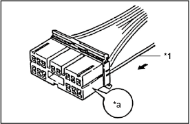 |
|
|
0.64 IDC Type |
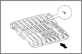 |
|
|
Insulation Displacement Connector |
 |
|
|
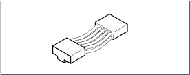
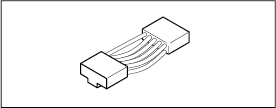
-
- NOTICE:
- After repairing, never let only one harness stretch.
- In case that it becomes short, do over again using the repair wire.
|
Good Example: |
 |
| Bad Example: |
 |
2. Double Locking Type Connector (with terminal retainer or double locking device)
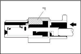
The connector is fitted with a terminal retainer, or a double locking device, it is in the temporary lock position at insert the terminal.
Type A (For 0.64III, 1.0, 1.0II, 1.3, 1.8, 2.3II 4.8 and 8.0 of Non-Waterproof Type Connector)
Insert the terminal.
- HINT:
- Make sure the terminal is positioned correctly.
- Insert the terminal with terminal retainer in the temporary lock position.
|
 |
|
|
- Insert the terminal until the locking clip locks firmly.
- HINT:
- Pull the terminal back gently to check whether it is locked correctly.
- If it cannot be inserted easily, check the terminal and the connector for damage.
-
- NOTE:
- If the terminal to locking clip does not lock firmly, the double locking device cannot lock or terminal retainer does not lock at full lock position so the terminal backs out from connector.
|
Example: |
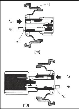 |
| *A |
Female |
| *B |
Male |
| *1 |
Double Locking Device |
| *a |
Good |
| *b |
Bad |
| *c |
Terminal in Short Position |
|
- Close terminal retainer or double locking device.
The connector is fitted with a terminal retainer, or a double locking device, return it to the full lock position.
|
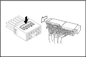 |
|
Push |
|
Close |
|
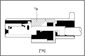 |
| *A |
Female |
| *a |
Full Lock Position |
|
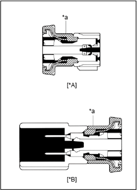 |
| *A |
Female |
| *B |
Male |
| *a |
Full Lock Position |
|
Type B (For 0.64, 1.8, 2.3, 2.3II, 4.8, 6.3 and 8.0 of Waterproof Type)
(For Male Connector)
- Insert the terminal.
- HINT:
- Make sure the terminal is positioned correctly.
- Insert the terminal with terminal retainer in the temporary lock position.
|
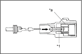 |
| *1 |
Terminal Locking Clip |
| *a |
Terminal Retainer at Temporary Lock Position |
|
- Insert the terminal until the locking clip locks firmly.
- HINT:
- Pull the terminal back gently to check whether it is locked correctly.
- If it cannot be inserted easily, check the terminal and the connector for damage.
|
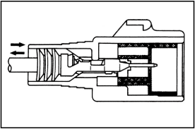 |
-
- NOTE:
- If the terminal to locking clip does not lock firmly, the double locking device cannot lock or terminal retainer does not lock at full lock position so the terminal backs out from connector.
|
Bad Example: |
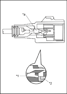 |
| *1 |
Terminal Locking Clip |
| *2 |
Terminal Retainer |
| *a |
Terminal in Short Position |
|
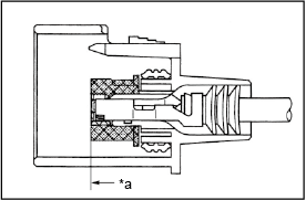
- "For Case 1"
Push the terminal retainer in to the full lock position.
|
[Case 1] |
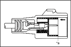 |
|
|
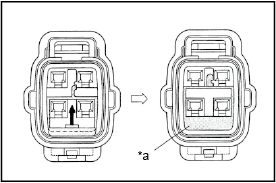
- "For Case 2"
Raise the terminal retainer up to the full lock position.
|
[Case 2] |
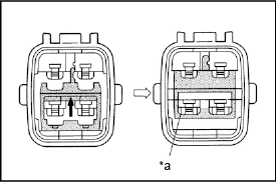 |
|
|
(For Female Connector)
Insert the terminal.
- HINT:
- Make sure the terminal is positioned correctly.
- Insert the terminal with terminal retainer in the temporary lock position.
|
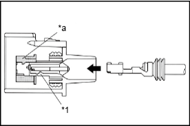 |
| *1 |
Terminal Locking Clip |
| *a |
Terminal Retainer at Temporary Lock Position |
|
- Insert the terminal until the locking clip locks firmly.
- HINT:
- Pull the terminal back gently to check whether it is locked correctly.
- If it cannot be inserted easily, check the terminal and the connector for damage.
|
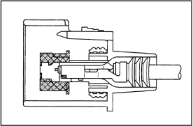 |
-
- NOTE:
- If the terminal to locking clip does not lock firmly, terminal retainer can not lock at full lock position so the terminal backs out from connector.
|
Bad Example: |
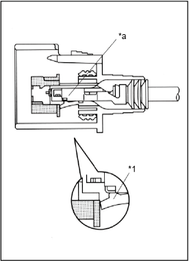 |
| *1 |
Terminal Locking Clip |
| *a |
Terminal in Short Position |
|
"For Case 1"
Push the terminal retainer in to the full lock position.
|
[Case 1] |
 |
|
|
- "For Case 2"
Raise the terminal retainer up to the full lock position.
|
[Case 2] |
 |
|
|
Type C (For 0.64 Type Connector)
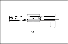
Insert the terminal.
- HINT:
- Make sure the terminal is positioned correctly.
- Insert the terminal with terminal retainer in the temporary lock position.
|
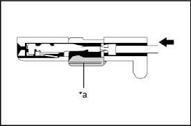 |
| *a |
Temporary Lock Position |
|
- Insert the terminal until the terminal lance locks firmly.
- HINT:
- Pull the terminal back gently to check whether it is locked correctly.
- If it cannot be inserted easily, check the terminal and the connector for damage.
-
- NOTE:
- If the terminal to terminal lance does not lock firmly, the double locking device cannot lock or terminal retainer does not lock at full lock position so the terminal backs out from connector.
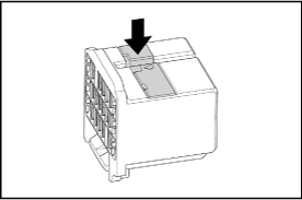
- Close terminal retainer.
The connector is fitted with a terminal retainer, return it to the full lock position.
|
 |
 |
|
|
SPECIAL EXAMPL
- First fit the section A.
|
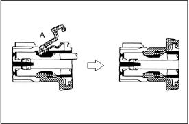 |
- Install the lock of the section A first.
|
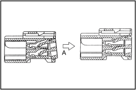 |
- Install the lock of the retainer and pull the white cover until you hear a click sound.
|
 |
- Install the convex part (A) of the outer part correctly to the section B of the inner part.
|
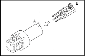 |
Insulation Displacement Connector
- w/ Cover : CLOSE COVER
-
- NOTICE:
- Securely lock it
|
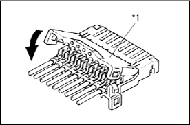 |
|
|
-
- HINT:
- When replacing it to a new connector, cut off the fixing band without leaving it.
|
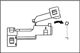 |
|
|
UNITE CONNECTOR
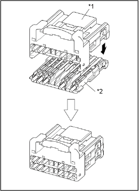
- Make the projection of the front lock of the upper housing meet the ditch of the front lock of the lower housing and fix the rear lock.
- NOTICE:
- After uniting, securely lock it for not leaving the rear lock arm deformed.
- Make sure that the terminals will not become loose by pulling the wires lightly.
|
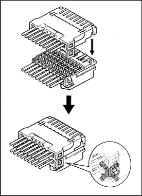 |
Insulation Displacement Connector (0.64 Type)
Install the upper housing to the lock housing.
- NOTICE:
- Securely Lock it.
- Be careful not to mistake the upper housing and lower housing when putting together.
|
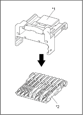 |
| *1 |
Lock Housing |
| *2 |
Upper Housign |
|
- Make the projection of the front lock of the upper housing attached lock housing meet tthe ditch of the front lock of the lower housing and fix the rear lock.
- NOTICE:
- Afteruniting, securely lock it for not leaving the rear lock arm deformed.
- Make sure that the terminals will not become loose by pulling the wires lightily.
- Be careful not to mistake the upper housing and lower housing when putting together.
|
 |
| *1 |
Upper Housing Attached Lock Housing |
| *2 |
Lower Housing |
|
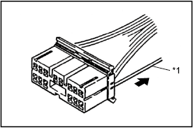
3. When properly installed, pulling gently on the wire lead will prove the terminal is locked in the connector.
|
 |
|
Pull Up |
| *1 |
Wire |
|
-
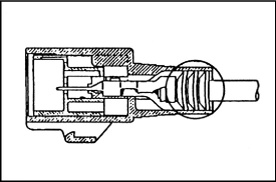
- NOTICE:
- If you working on the waterproof type, make sure that a rubber plug or a terminal gasket is inserted into the housing securely.
|
 |
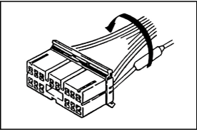
4. Secure the Repaired Wire to the Harness
-
- If the wire is not in the conduit, or secured by other means, wrap vinyl tape around the bundle to keep it together with the other wires.
|
 |
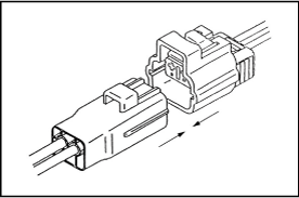
5. Connect Connector
- Fit the male connector to the female terminal.
- NOTICE:
- Do not twist the connector when fitting.
- Insert it until fully locked.
|
 |
| Extra. Special handling for the wires that are protected with CFWs. |
|
1. When a terminal or multiple terminals are replaced:
- If wires are protected with CFWs and the extra wire length shown in the illustration is shorter than 18 mm (A), use the following procedure for proper repair.
- NOTICE:
- The procedures instructed below are supplements to the original terminal replacement procedure. To replace terminals, refer to the original procedure from steps 1 to 4 as well.
|
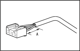 |
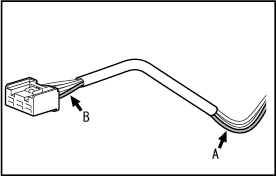
- Cut the applicable wire(s) at somewhere around A.
- Cut the applicable wire(s) at somewhere around B, and then remove the terminal(s) from the connector housing.
- HINT:
- Do not remove the cut wires from the CFW so as to prevent other wires from being damaged.
|
 |
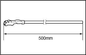
- Prepare for new repair wire(s) with length of 500 mm.
|
 |
- If multiple terminals need to be replaced, change the cut points of the new wires as shown in the illustration.
|
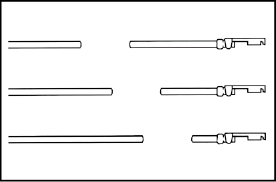 |
- After the terminal(s) is replaced, bind the wire(s) of the terminal(s) to the CFW protector(s) by wrapping silicon tape around them.
|
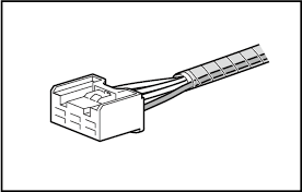 |
|
2. When all the terminals need to be replaced, or if CFWs protectors have been broken:
- NOTICE:
- The procedures instructed below are supplements to the original terminal replacement procedure. To replace terminals, refer to the original procedure from steps 1 to 4 as well.
- Cut all the wires at somewhere around A, and remove all the terminals from the connector housing.
|
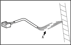 |
- Prepare for new repair wires with length of 500 mm.
|
|
- Change the cut points of the new wires as shown in the illustration.
|
|
- After all the terminals are inserted into the connector housing, wrap a convoluted tube or similar, instead of CFWs, around the wires to bind them together.
- If wire harness clamps had been used, install new clamps onto the convoluted tube.
|
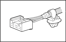 |
| HOW TO INSTALL AND REMOVE SPECIAL CONNECTORS Low Fit and Lever Type Connector |
[Case 1]
1. Cut the connection of the connector
- Push the place indicated by the arrow.
- The lock is released and lever is lifted up.
|
 |
|
|
- Lift the lever up until it stops.
|
 |
- Cut the connection of the connector.
-
- NOTICE:
- Do not hold the wire harness to pull it.
|
 |
2. Connect the connector
- Connect the connector in the condition that the lever is fully lifted up.
-
- HINT:
- If the lever is locked at the lower position, follow the procedure [Case 1]. (1) to (3) and lift the lever up fully.
|
 |
|
|
- Hold the connector to prevent it from slip off and push it down until you hear a click to lock it.
|
 |
|
|
- Confirm that the lever is securely locked.
|
 |
|
|
[Case 2]
1. Cut the connection of the connector
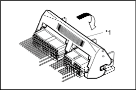
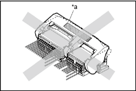
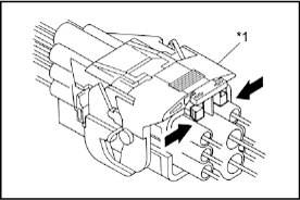
- Hold the area indicated by the arrow in the illustration
- The lock is released and the lever is lifted up.
|
 |
|
|
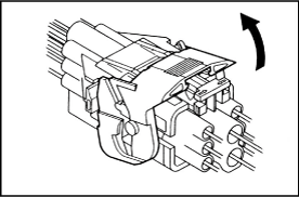
- Lift the lever up fully.
|
 |
- Cut the connection of the connector.
-
- NOTICE:
- Do not hold the wire harness to pull it.
|
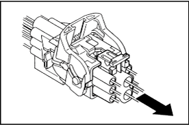 |
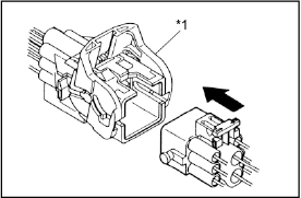
2. Connect the connector
- Connect the connector in the condition that the lever is fully lifted up.
|
 |
|
|
- Hold the connector to prevent it from slip off and push it down until you hear a click to lock it.
|
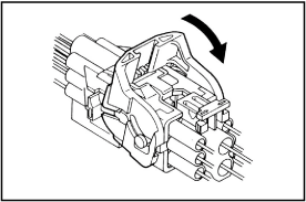 |
- Confirm that the lever is securely locked.
|
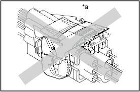 |
|
|
[Case 3]
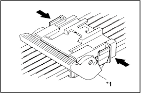
1. Cut the connection of the connector
- Pick the part indicated in the illustration by fingers.
- The lock is released and the lever is lifted up.
|
 |
|
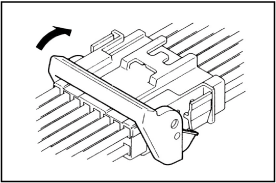
|
- Lift the lever up fully.
|
 |
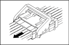
- Cut the connection of the connector.
-
- NOTICE:
- Do not hold the wire harness to pull it.
|
 |
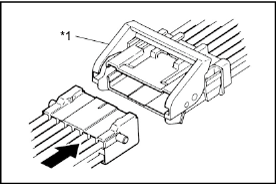
2. Connect the connector
- Connect the connector in the condition that the lever is fully lifted up.
-
- HINT:
- If the lever is locked at the lower position, follow the procedure [Case 3]. (1) to (3) and lift the lever up fully.
|
 |
|
|
- Hold the connector to prevent it from slip off and push it down until you hear a click to lock it.
|
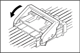 |
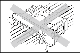
- Confirm that the lever is securely fitted
|
 |
|
|
The connector with secondary locking device
1. Area used
- Wire harness for SRS airbag deployment
|
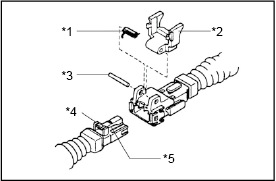 |
| *1 |
Coil spring |
| *2 |
Double locking device pin |
| *3 |
Pin |
| *4 |
Convex part |
| *5 |
Primary locking device |
|
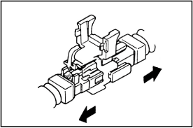
2. Cut the connection of the connector.
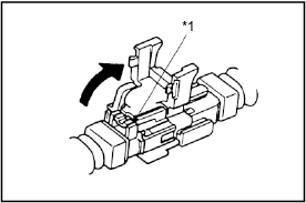
- Release the double locking.
|
 |
|
|
- Release the primary locking and separate the connector.
-
- NOTICE:
- Do not hold the wire harness to pull it.
|
 |
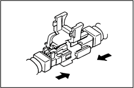
3. Connect the connector
- Install the primary locking device and connect the connector.
|
 |
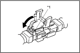
- Install the double locking device.
-
- NOTICE:
- The double locking device can not be installed unless the primary locking device is installed.
|
 |
|
|
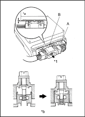
Connector fixed by bolts
1. Area used
- Engine control computer harness
2. Cut the connection of the connector.
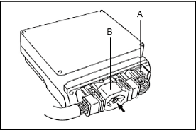
- Remove the connector A.
- Loose the bolt using a tool like driver until the connector B can be removed by hand and separate the connector.
-
- HINT:
- If the bolt can not be removed, roll it while pulling forward.
|
 |
3. Connection of the connector
- Temporarily fit the connector B.
- Tighten the bolt by using tool like driver and fit the connector B completely.
-
- NOTICE:
- Tighten the bolt until feeling it lighter. Then confirm that the width of chink of the connector B is less than 1mm.
- The bolt can be rolled after it is fitted.
- If the impact wrench is used, do not let it rolling more than three seconds. (The housing may be deformed by generated heat)
- Be sure and connect the connector B straight. Do not incline it while connecting.
- Connect the connector A.
|
 |
| *1 |
Bolt |
| *a |
Lass than 1mm |
| *b |
Cross-section of the bolt |
|
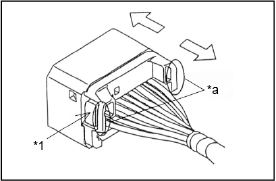
1. Cut the connection of the connector
- Push down on locking arm to unlock. Then hold the back ribs of connector to remove connector.
- Cut the Connection of the connector.
-
- NOTICE:
- Do not hold the wire harness to pull it.
|
 |
| *1 |
Locking Arm |
| *a |
Hold back rib to pull connector |
|
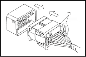
2. Connect the Connector
- Align the direction of locking feature in same direction and mate the connector holding the back ribs in straight direction.
- Insert it until a lock securely locks, and pull the connector lightly after the insertion, and confirm that a lock is enabled.
|
 |
|
|
|