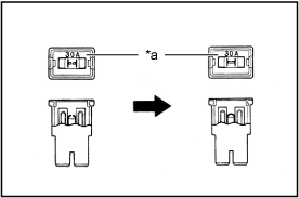
|
WIRE HARNESS REPAIR INTRODUCTION
This manual provides instruction in the following repairs:
- How to Inspect for System Inspection
- Circuit Protection
- Terminal and Connector Repair Procedure
- NOTICE:
- When inspecting or repairing the SRS AIRBAG, be sure to carefully read the precautionary instructions and procedure in the Repair Manual for the applicable model.
- After any electrical repair is made, always test the circuit by operating the devices in the circuit. This confirms not only that the repair is correct, but also that the cause of the complaint was correctly identified.
- Terminal type number name
The terminal type number naming system has changed:
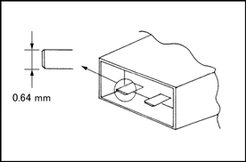
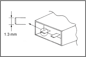
the metric system will be used in place of the inch system. To be more specific, male tab width "in millimeters" will be used as terminal type number from now on -- in place of male tab wwidth in inches which has been in use so far.
Below is a table of comparison:
Old terminal type No.
(inch) |
|
New terminal type No.
(mm) |
| 025 |
-> |
0.64 |
| 040 (II, III, IV) |
-> |
1.0 (II, III, IV) |
| 050 |
-> |
1.3 |
| 060 |
-> |
1.5 |
| 070 (II) |
-> |
1.8 (II) |
| 090 (II) |
-> |
2.3 (II) |
| 110 |
-> |
2.8 |
| 187 |
-> |
4.8 |
| 250 (II) |
-> |
6.3 (II) |
| 305 |
-> |
7.7 |
| 312 |
-> |
8.0 |
| 375 |
-> |
9.5 |
For those connectors which are not shown above, the terminal type numbers remain unchanged.
|
 |
- What is Wire Harness?
-
The wire harness (W/H) is systems of electric wires for automobiles to connect all the electronics parts in automobile electrically and work them. As more electronics parts are introduced in automobiles recently, the electric wires used for the wire harness are increasing in number and the structure is becoming more complicated. As a result of that, there are hundreds of connectors, which is the parts which connects wires mechanically and electrically, in one vehicle. Therefore, numbers of the connector terminal (Terminal) or the connector housing (Housing) are designed to meet many kinds of uses of circuits. Various components have been improved to ensure the product reliability or realize a wider space in the vehicles.
|
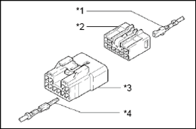 |
| *1 |
Terminal (Female) |
| *2 |
Housing (Female) |
| *3 |
Housing (Male) |
| *4 |
Terminal (Male) |
|
- Wire Harness Components
-
Wire harness mainly consists of wires, terminals, or housings.
There are various components are designed for many parts of vehicles, such as one with high heat-resistance, water-resistance, or bending ability, ones have different current capacities, or ones are hardly influenced by electromagnetic noise.
|
Wire
Harness
(W/H) |
Electric Wire |
| Terminal |
| Housing |
| J/B (Junction Block) |
| R/B (Relay Block) |
| Other |
|
- Electric Wire
-
The electric wires used for the wire harness consists of the conductor made from numbers of twisted mild copper or aluminum wire with a diameter of less than 0.5 mm and the insulator surrounding the conductor.
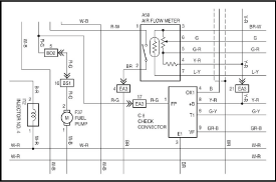
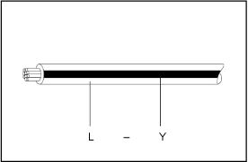
The insulator is generally made from vinyl chloride and covers the conductor with even thickness. The insulators are color-coded in order to distinguish each wire. The base colors or the stripe patterns are used to make difference between insulators. Each color of wires is indicated by the abbreviation in the repair manual and the electrical wiring diagram.
- Copper wires:
| B=Black |
Y=Yellow |
| G=Green |
BE=Beige |
| L=Blue |
BR=Brown |
| O=Orange |
DG=Dark Gray |
| P=Pink |
GR=Gray |
| R=Red |
LG=Light Green |
| V=Violet |
SB=Sky Blue |
| W=White |
|
Aluminum wires:
|
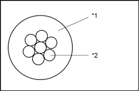 |
| *1 |
Insulator |
| *2 |
Copper Wires (Conductor) |
|
 |
-
The first letter indicates the basic wire color and the second letter indicates the color of the stripe.
|
Example:L-Y |
 |
|
|
- Terminal and housing
- Terminal connects wires and housing insulates connecting parts.
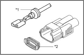
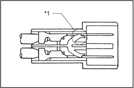
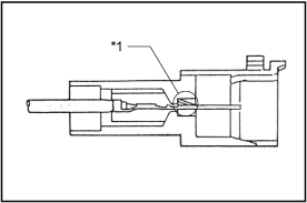
There are the male terminal and the female terminal. The types of terminals are decided by tab width of male terminal. And the terminal with the rubber plug or the rubber ring is used in the part, such as the engine compartment, which become wet. For the circuit with slight current at EFI system or ABS system, the gold-plated terminal is introduced for ensuring reliabilities.
As the number of the circuit is increasing recently, there are new types of parts introduced. For example, there is the hybrid type housing, which is a combination of terminals with different tab width, such as the power source terminal or the signal terminal. Also, new type of connector such as the double lock housing, which is designed with the retainer in addition to the lance to prevent terminal from slipping off, is available. The new type of connectors are produced to realize higher product reliabilities and utilized widely recently. The major characteristics of these new connectors are shown in the table 1.
There are two types of lances: housing lance, which is inside the housing and terminal lance, which is inside the terminal.
|
 |
 |
| *1 |
Rubber Plug |
| *2 |
Rubber Ring |
|
 |
|
|
 |
|
|
|
What is a CFW?
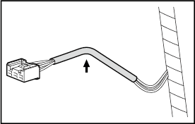
- A CFW (Compression Forming Wire-harness) is a wire harness protector made of non woven fabric and formed by hot compression molding. One of the two types of CFWs offers desired routings where wire harnesses should go through, and the other insulates noises that are likely to occur when wire harnesses and the vehicle body interfere with each other.
If the wire harness is protected with CFWs, refer to the cautions listed below for handling.
- Do not deform or fold.
- Store at normal temperature and humidity.
- Protect from dirt or metal flakes. (Do not place or store in dusty locations)
- Protect from water. (Do not store in humid locations. Also, store in indoor locations to protect from rain)
- Protect from fluids and oil/grease.
Liquids: Battery fluids, washer fluids, LLC etc.
Oil/grease: Lubricants, silicon oil, engine oil, brake fluids etc.
- Do not cut CFWs to repair wire harnesses.
|
 |
| Table 1 : Characteristics of the new types of connector (Improvement) |
| Characteristics (Improvement) |
Note |
- Double Lock
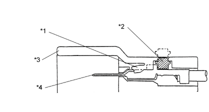 |
If terminal is not inserted to housing correctly, the retailer does not fit.
|
| *1 |
Lance (Primary Lock) |
| *2 |
Retainer (Double Lock) |
| *3 |
Housing |
| *4 |
Terminal |
|
- Extension of Housing
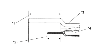 |
This is to prevent deformation of the terminal when it is inserted diagonally.
|
| *1 |
Extension |
| *2 |
Shortening |
| *3 |
Housing |
| *4 |
Terminal |
|
- Change of Contact Structure and Introduction of Box-Shaped Structure
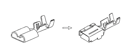 |
Expansion of contact section
Stabilization of contact pressure |
- Change of Locking Shape
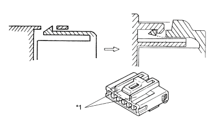 |
This improves the close fit of locking and you can hear the click sound and feel that the connector is completely installed.
|
|
|
| HOW TO PERFORM FOR SYSTEM INSPECTION |
This inspection procedure is a simple troubleshooting which should be carried out on the vehicle during system operation and is based on the assumption of system component trouble.
Always inspect the trouble taking the following items into consideration:
- Ground point fault
- Open or short circuit of the wire harness
- Connector or terminal connection fault
- Fuse or fusible link fault
- NOTICE:
- This is an on-vehicle inspection during system operation.
Therefore, inspect the trouble with due regard for safety.
- If connecting the battery directly, be careful not to cause a short circuit, and select the applicable voltage.
|
1. Voltage Check
- Establish conditions in which voltage is present at the check point.
Example:
| [A] |
- |
Ignition SW on |
| [B] |
- |
Ignition SW and SW 1 on |
| [C] |
- |
Ignition SW, SW 1 and Relay on (SW 2 off) |
- Using a voltmeter, connect the negative (-) lead to a good ground point or negative (-) battery terminal and the positive (+) lead to the connector or component terminal. This check can be done with a test bulb instead of a voltmeter.
|
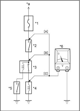 |
| *1 |
Fuse |
| *2 |
SW1 |
| *3 |
Relay |
| *4 |
Solenoid |
| *5 |
SW2 |
| *6 |
Voltmeter |
| *a |
To Ignition SW IG Terminal |
|
|
2. Continuity and Resistance Check
- Disconnect the battery terminal or wire so there is no voltage between the check points.
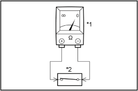
- Contact the two leads of an ohmmeter to each of the check points.
|
 |
|
|
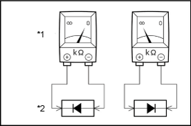
- If the circuit has diodes, reverse the two leads and check again.
When touching the negative (-) lead to the diode positive (+) side and the positive (+) lead to the negative (-) side, there should be continuity. When touching the two leads in reverse, there should be no continuity.
- HINT:
-
- Specifications may vary depending on the type of tester, so refer to the tester's instruction manual before performing the inspection.
|
 |
|
|
-
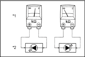
Check LED (Light Emitting Diode) in the same manner as that for diodes.
- HINT:
-
- Use a tester with a power source of 3V or greater to overcome the circuit resistance.
- If a suitable tester is not available, apply battery voltage and check that the LED lights up.
|
 |
|
|
- Use a volt/ohmmeter with high impedance (10kΩ/V minimum) for troubleshooting of the electrical circuit.
|
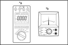 |
| *a |
Digital Type |
| *b |
Analog Type |
|
|
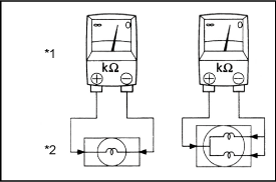
3. Bulb Check
- Remove the bulb.
- There should be continuity between the respective terminals of the bulb together with a certain amount of resistance.
- Apply the two leads of the ohmmeter to each of the terminals.
- Apply battery voltage and check that the bulb light up.
|
 |
|
|
|
4. Finding a Short Circuit
- Remove the blown fuse and eliminate all loads from the fuse.
- Connect a test bulb in place of the fuse.
- Establish conditions in which the test bulb comes on.
Example:
| [A] |
- |
Ignition SW on |
| [B] |
- |
Ignition SW and SW 1 on |
| [C] |
- |
Ignition SW, SW 1 and Relay on (Connect the Relay) and SW 2 off (or disconnect SW 2) |
- Disconnect and reconnect the connectors while watching the test bulb. The short lies between the connector where the test bulb stays lit and the connector where the bulb goes out.
- Find the exact location of the short by lightly shaking the problem wire along the body.
- CAUTION:
-
- Do not open the cover or the case of the ECU unless absolutely necessary. (If the IC terminals are touched, the IC may be destroyed by static electricity.)
- When replacing the internal mechanism (ECU part) of the digital meter, be careful that no part of your body or clothing comes in contact with the terminals of leads from the IC, etc. of the replacement part (spare part).
|
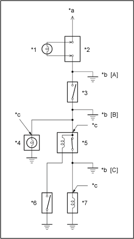 |
| *1 |
Test Bulb |
| *2 |
Fuse Case |
| *3 |
SW1 |
| *4 |
Light |
| *5 |
Relay |
| *6 |
SW2 |
| *7 |
Solenoid |
| *a |
To Ignition SW IG Terminal |
| *b |
Short |
| *c |
Disconnect |
|
All electrical circuits are protected against excessive loads which might occur because of shorts or overloads in the wiring system. Such protection is provided by a fuse, circuit breaker, or fusible link, A short circuit may cause a fuse to blow or a circuit breaker to open.
|
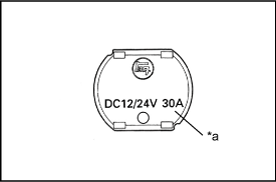
RESET CIRCUIT BREAKER
1. Remove Circuit Breaker
- Disconnect the negative (-) cable from the battery.
- Remove the circuit breaker.
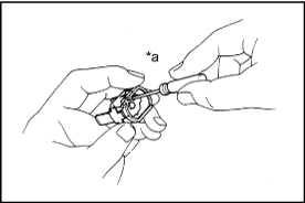
2. Reset Circuit Breaker
- Insert the needle into the reset hole and push it.
|
 |
|
|
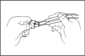 |
- Using an ohmmeter, check that there is continuity between both terminals of the circuit breaker.
- If continuity is not as specified, replace the circuit breaker.
- HINT:
-
- If replacing the circuit breaker, be sure to replace it with a breaker with an equal amperage rating.
|
 |
|
|
|
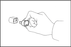
3. Install Circuit Breaker
-
Install the circuit breaker.
-
Connect the negative (-) cable to the battery
- HINT:
-
- If a circuit breaker continues to cut out, a short circuit is indicated. Have the system checked by a qualified technician.
|
 |
|
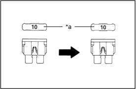
REPLACEMENT OF FUSE AND FUSIBLE LINK
- HINT:
-
- If replacing the fuse or fusible link, be sure to replace it with a fuse or fusible link with an equal amperage rating.
|
 |
|
|
- NOTICE:
-
- Turn off all electrical components and the ignition switch before replacing a fuse or fusible link. Do not exceed the fuse or fusible link amperage rating.
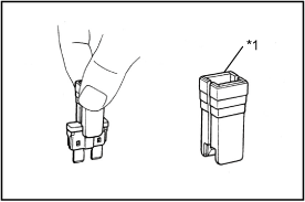
- Always use a fuse puller for removing and inserting a fuse. Remove and insert straight in and out without twisting. Twisting could force open the terminals too much, resulting in a bad connection.
-
If a fuse or fusible link continues to blow, a short circuit is indicated. The system must be checked by a qualified technician.
- HINT:
- The puller is located at Junction Block No.2.
|
 |
|
|
|