- No SPD (speed sensor) signal while ECM detects NC (transmission counter gear) signal
- Park/Neutral position switch is OFF (When shift lever is in other than P and N positions)
- Transfer lever is in other than N position (4WD)
| Last Modified: 7-3-2017 | 6.8:8.0.40 | Doc ID: RM000000O6600HX |
| Model Year Start: 2007 | Model: LX470 | Prod Date Range: [08/2006 - ] |
| Title: 2UZ-FE ENGINE CONTROL SYSTEM: SFI SYSTEM: P0500; Vehicle Speed Sensor "A"; 2007 MY LX470 [08/2006 - ] | ||
|
DTC |
P0500 |
Vehicle Speed Sensor "A" |
DESCRIPTION
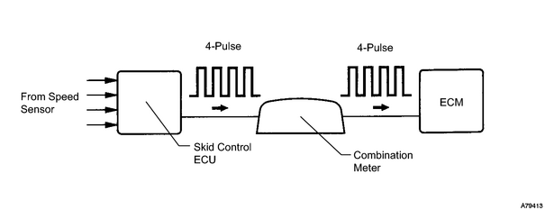
The speed sensor detects the wheel speed and sends the appropriate signals to the skid control ECU. The skid control ECU converts these wheel speed signals into a 4-pulse signal and outputs it to the ECM via the combination meter. The ECM determines the vehicle speed based on the frequency of these pulse signals.
|
DTC No. |
DTC Detection Condition |
Trouble Area |
|---|---|---|
|
P0500 |
The ECM detects following conditions simultaneously for 1 second (1 trip detection logic): |
|
MONITOR DESCRIPTION
The ECM assumes that the vehicle is driven when the park/neutral position switch is OFF and it has been over 4 seconds since the actual vehicle speed was 9 km/h (6 mph) or more.
If there is no signal from the vehicle speed sensor when these conditions are satisfied, the ECM concludes that there is a fault in the vehicle speed sensor. The ECM will turn on the MIL and a DTC is set.
MONITOR STRATEGY
|
Related DTCs |
P0500: Vehicle speed sensor "A" pulse input error |
|
Required Sensors/Components (Main) |
Vehicle speed sensor |
|
Required Sensors/Components (Related) |
Park/Neutral position switch, Engine coolant temperature sensor, Combination meter |
|
Frequency of Operation |
Continuous |
|
Duration |
5 seconds |
|
MIL Operation |
Immediate |
|
Sequence of Operation |
None |
TYPICAL ENABLING CONDITIONS
|
The monitor will run whenever this DTC is not present |
- |
|
Vehicle speed |
9 km/h (6 mph) or more |
|
Park/neutral position switch |
OFF |
TYPICAL MALFUNCTION THRESHOLDS
|
Sensor signal |
No pulse input |
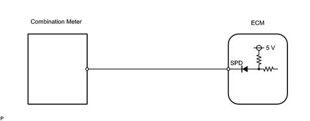
WIRING DIAGRAM
INSPECTION PROCEDURE
HINT:
Read freeze frame data using the intelligent tester. Freeze frame data records the engine conditions when a malfunction is detected. When troubleshooting, freeze frame data can help determine if the vehicle was running or stopped, if the engine was warmed up or not, if the air fuel ratio was LEAN or RICH, and other data from the time the malfunction occurred.
PROCEDURE
|
1. |
CHECK OPERATION OF SPEEDOMETER |
(a) Drive the vehicle and check if the operation of the speedometer in the combination meter is normal.
HINT:
The vehicle speed sensor is operating normally if the speedometer display is normal.
| NG |

|
|

|
2. |
INSPECT ECM (SPD VOLTAGE) |
(a) Move the shift lever to the neutral position.
(b) Jack up the vehicle.
(c) Turn the ignition switch ON.
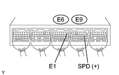
(d) Check the voltage between the specified terminals of the E6 and E9 ECM connectors as the wheel is turned slowly.
Standard:
|
Tester Connection |
Specified Condition |
|---|---|
|
E9-8 (SPD) - E6-1 (E1) |
Generated intermittently |
HINT:
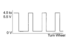
The output voltage should fluctuate up and down similarly to the diagram when the wheel is turned slowly.
| NG |
|
REPAIR OR REPLACE HARNESS OR CONNECTOR (COMBINATION METER - ECM) |
| OK |
|

|

|