- Throttle actuator duty-cycle is 80% or more
- Throttle actuator current is below 0.5 A or less
| Last Modified: 7-3-2017 | 6.8:8.0.40 | Doc ID: RM000000PFU02RX |
| Model Year Start: 2007 | Model: LX470 | Prod Date Range: [08/2006 - ] |
| Title: 2UZ-FE ENGINE CONTROL SYSTEM: SFI SYSTEM: P2102,P2103; Throttle Actuator Control Motor Circuit Low; 2007 MY LX470 [08/2006 - ] | ||
|
DTC |
P2102 |
Throttle Actuator Control Motor Circuit Low |
|
DTC |
P2103 |
Throttle Actuator Control Motor Circuit High |
DESCRIPTION
The throttle actuator is operated by the ECM and it opens and closes the throttle valve.
The opening angle of the throttle valve is detected by the throttle position sensor which is mounted on the throttle body. The throttle position sensor provides feedback to the ECM. This feedback allows the ECM to control the throttle actuator and monitor the throttle opening angle as the ECM responds to driver inputs.
HINT:
This Electronic Throttle Control System (ETCS) does not use a throttle cable.
|
DTC No. |
DTC Detection Conditions |
Trouble Areas |
|---|---|---|
|
P2102 |
Following conditions are met for 2 seconds (1 trip detection logic): |
|
|
P2103 |
Either of following conditions is met (1 trip detection logic):
|
|
MONITOR DESCRIPTION
The ECM monitors the flow of electrical current through the electronic throttle actuator, and detects malfunctions or open circuits in the throttle actuator based on the value of the electrical current. When the current deviates from the standard values, the ECM concludes that there is a fault in the throttle actuator. Or, if the throttle valve is not functioning properly (for example, stuck ON), the ECM concludes that there is a fault and illuminates the MIL and sets a DTC.
Example:
The ECM determines that the current has deviated from the standard values when one of the following is detected: 1) the current is more than 10 A, or 2) the actuator driving duty ratio exceeds 80% and the current is less than 0.5 A. Then the ECM turns on the MIL and a DTC is set.
This monitor runs after the engine is started, idled for 5 seconds and then quickly revved at a high rpm several times.
MONITOR STRATEGY
|
Related DTCs |
P2102: Throttle actuator current (low current) P2103: Throttle actuator current (high current) |
|
Required Sensors/Components (Main) |
Throttle actuator (throttle body) |
|
Required Sensors/Components (Related) |
None |
|
Frequency of Operation |
Continuous |
|
Duration |
2 seconds |
|
MIL Operation |
Immediate |
|
Sequence of Operation |
None |
TYPICAL ENABLING CONDITIONS
|
Monitor will run whenever these DTCs are not present |
None |
P2102:
|
Throttle actuator |
ON |
|
Duty ratio to open throttle actuator |
80% or more |
|
Throttle power supply |
8 V or more |
|
Motor current change during latest 0.016 seconds |
Less than 0.2 A |
P2103:
|
Throttle actuator |
ON |
|
Either of the following conditions 1 or 2 is met: |
- |
|
1. Throttle actuator power supply |
8 V or more |
|
2. Throttle actuator power |
ON |
|
Battery voltage |
8 V or more |
|
Starter |
OFF |
TYPICAL MALFUNCTION THRESHOLDS
P2102:
|
Throttle actuator current |
Less than 0.5 A |
P2103:
|
When either condition below is met: |
- |
|
Hybrid IC diagnosis signal |
Fail |
|
Hybrid IC current limiter port |
Fail |
FAIL-SAFE
When any of these DTCs, as well as other DTCs relating to Electronic Throttle Control System (ETCS) malfunctions, are set, the ECM enters fail-safe mode. During fail-safe mode, the ECM cuts the current to the throttle actuator off, and the throttle valve is returned to a 7°throttle angle by the return spring. The ECM then adjusts the engine output by controlling the fuel injection (intermittent fuel-cut) and ignition timing, in accordance with the accelerator pedal opening angle, to allow the vehicle to continue at a minimal speed.
If the accelerator pedal is depressed firmly and gently, the vehicle can be driven slowly.
Fail-safe mode continues until a pass condition is detected, and the ignition switch is then turned OFF.
WIRING DIAGRAM
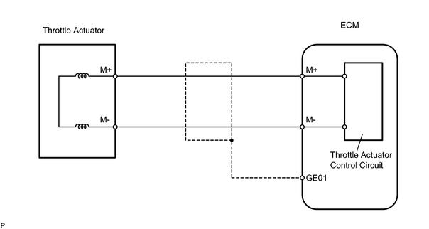
INSPECTION PROCEDURE
HINT:
- Read freeze frame data using the intelligent tester. Freeze frame data records the engine conditions when malfunctions are detected. When troubleshooting, freeze frame data can help determine if the vehicle was running or stopped, if the engine was warmed up or not, if the air fuel ratio was lean or rich, and other data from the time the malfunction occurred.
- The throttle actuator current (THROTTLE MOT) and the throttle actuator duty ratio (THROTTLE OPN / THROTTLE CLS) can be read using the intelligent tester. However, the ECM shuts off the throttle actuator current when the ETCS malfunctions.
PROCEDURE
|
1. |
INSPECT THROTTLE BODY (RESISTANCE OF THROTTLE ACTUATOR) |
|
(a) Disconnect the T24 throttle body connector. (b) Measure the resistance of the throttle actuator. Standard resistance:
|
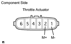
|
| NG |

|
|

|
2. |
CHECK HARNESS AND CONNECTOR (THROTTLE ACTUATOR - ECM) |
(a)
Check harness and connector
![2007 MY LX470 [08/2006 - ]; INTRODUCTION: HOW TO TROUBLESHOOT ECU CONTROLLED SYSTEMS: ELECTRONIC CIRCUIT INSPECTION PROCEDURE](../../../../stylegraphics/info.gif "2007 MY LX470 [08/2006 - ]; INTRODUCTION: HOW TO TROUBLESHOOT ECU CONTROLLED SYSTEMS: ELECTRONIC CIRCUIT INSPECTION PROCEDURE") .
.
| NG |
|
|
|
3. |
INSPECT THROTTLE BODY (VISUALLY CHECK THROTTLE VALVE) |
(a) Check between the throttle valve and the housing for foreign objects. Also check if the valve can open and close smoothly.
OK:
The throttle valve is not contaminated by foreign objects and can move smoothly.
| NG |
|
| OK |
|

|

|