| Last Modified: 7-3-2017 | 6.8:8.0.40 | Doc ID: RM000000SLB00DX |
| Model Year Start: 2007 | Model: LX470 | Prod Date Range: [08/2006 - ] |
| Title: 2UZ-FE ENGINE MECHANICAL: TIMING BELT: INSTALLATION; 2007 MY LX470 [08/2006 - ] | ||
INSTALLATION
1. INSTALL TIMING BELT
(a) Check the No. 1 and No. 2 belt idlers.
(1) Visually check the seal portion of the idler pulley for oil leakage.
- If leakage is found, replace the idler.
(2) Check that the idler turns smoothly.
- If necessary, replace the idler.
|
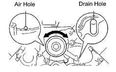
(b) Check the water pump. (1) Visually check the air hole and water hole for coolant leakage.
(2) Turn the pulley, and check that the water pump bearing moves smoothly and quietly.
|
|
(c) Remove any oil or water on the crankshaft, oil pump pulley, water pump pulley, No. 1 and No. 2 belt idlers. Keep them clean.
NOTICE:
Only wipe the pulleys. Do not use any cleansing agents on the pulleys.
(d) Set the No. 1 cylinder to TDC/compression.
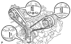
(1) Turn the hexagon head portion of the camshaft to align the timing marks of the camshaft timing pulleys and timing belt plates.
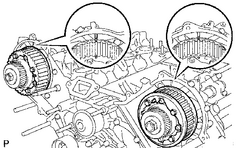
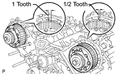
HINT:
Turn the camshaft timing pulleys slightly clockwise to make installation of the timing belt easier.
Camshaft timing pulley LH:
1/2 of a tooth
Camshaft timing pulley RH:
1 tooth
|
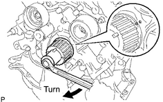
(2) Using the crankshaft damper bolt, turn the crankshaft to align the timing marks of the crankshaft timing pulley and oil pump body. |
|
|
(3) Remove any oil or water on each pulley. Keep them clean. NOTICE: Only wipe the pulleys. Do not use cleaning agents on the pulleys. |
|
(4) Face the front mark (arrow) on the belt forward.
(5) Connect the belt to the crankshaft timing pulley. Align the installation mark on the belt with the timing mark of the crankshaft timing pulley.
(6) Connect the belt to the No. 2 belt idler.
(7) Connect the belt to the camshaft timing pulley LH. Align the installation mark on the belt with the timing mark of the camshaft timing pulley.
(8) Connect the belt to the water pump pulley.
(9) Connect the belt to the camshaft timing pulley RH. Align the installation mark on the belt with the timing mark of the camshaft timing pulley.
(10) Connect the timing belt to the No. 1 belt idler.
|
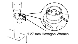
(e) Set the belt tensioner. (1) Using a press, slowly press in the push rod using 981 to 9,807 N (100 to 1,000 kgf, 220 to 2,205 lbf) of pressure. (2) Align the holes of the push rod and housing. Pass a 1.27 mm hexagon wrench through the holes to keep the setting position of the push rod. (3) Release the press. (4) Install the dust boot to the belt tensioner. |
|
|
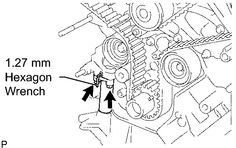
(f) Install the belt tensioner. (1) Temporarily install the belt tensioner with the 2 bolts. (2) Alternately tighten the 2 bolts. Torque: 26 N·m {265 kgf·cm, 19ft·lbf} (3) Using pliers, remove the 1.27 mm hexagon wrench from the belt tensioner. |
|
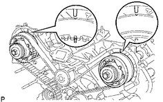
(g) Check the valve timing.
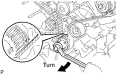
(1) Using the crankshaft damper bolt, slowly turn the crankshaft timing pulley 2 revolutions from TDC to TDC.
NOTICE:
Always turn the crankshaft pulley clockwise.
|
(2) Check that each pulley aligns with the timing marks as shown in the illustration.
|
|
(3) Remove the crankshaft damper bolt.
2. INSTALL CRANKSHAFT POSITION SENSOR PLATE
|
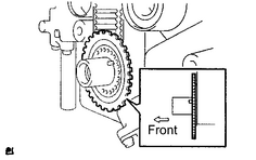
(a) Install the sensor plate as shown in the illustration. NOTICE: Be careful of the installation direction. |
|
3. INSTALL NO. 1 TIMING BELT COVER
|
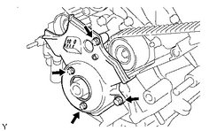
(a) Install the timing belt cover with the 4 bolts. Torque: 7.5 N·m {76 kgf·cm, 66in·lbf} |
|
4. INSTALL CRANKSHAFT DAMPER SUB-ASSEMBLY
|
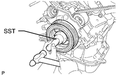
(a) Align the damper set key with the key groove of the crankshaft damper. |
|
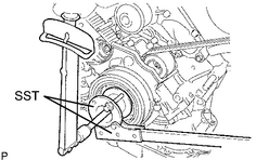
(b) Using SST and a hammer, tap in the damper.
SST: 09223-46011
|
(c) Using SST, install the damper bolt. SST: 09213-70011 09213-70020 SST: 09330-00021 Torque: 245 N·m {2,498 kgf·cm, 181ft·lbf} |
|
5. INSTALL FAN BRACKET SUB-ASSEMBLY
|
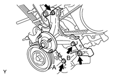
(a) Install the fan bracket with the 2 bolts and 2 nuts. Torque: 16 N·m {163 kgf·cm, 12ft·lbf} for 12 mm head Torque: 32 N·m {326 kgf·cm, 24ft·lbf} for 14 mm head Bolt length: 106 mm (4.17 in.) for 12 mm head bolt A 114 mm (4.49 in.) for 14 mm head bolt B |
|
6. INSTALL DRIVE BELT TENSIONER ASSEMBLY
|
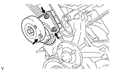
(a) Install the belt tensioner with the bolt and 2 nuts. Torque: 16 N·m {163 kgf·cm, 12ft·lbf} HINT: Use a bolt that is 106 mm (4.17 in.) in length. |
|
7. INSTALL NO. 2 TIMING BELT COVER SUB-ASSEMBLY
|
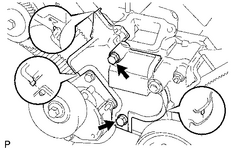
(a) Set the belt cover by matching the claws and pin with each part. |
|
(b) Install the timing belt cover with the 2 bolts.
Torque:
16 N·m {163 kgf·cm, 12ft·lbf}
HINT:
Use bolts that are 106 mm (4.17 in.) in length.
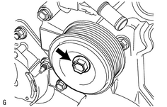
8. INSTALL NO. 2 IDLER PULLEY SUB-ASSEMBLY
|
(a) Install the idler pulley and cover plate with the bolt. Torque: 39 N·m {398 kgf·cm, 29ft·lbf} |
|
9. INSTALL NO. 3 TIMING BELT COVER SUB-ASSEMBLY LH
|
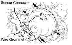
(a) Install the gasket to the belt cover. |
|
(b) Pass the camshaft position sensor wire through the cover hole.
(c) Install the cover with the 4 bolts.
Torque:
7.5 N·m {76 kgf·cm, 66in·lbf}
(d) Install the wire grommet to the belt cover.
(e) Install the sensor connector to the sensor holder.
(f) Connect the sensor connector.
(g) Install the sensor wire to the wire clamp on the cover.
(h) Install the engine wire to the 2 wire clamps on the cover.
10. INSTALL OIL COOLER PIPE
|
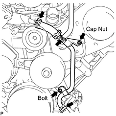
(a) Connect the 3 water by-pass hoses as shown in the illustration. |
|
(b) Install the oil cooler pipe to the cover with the cap nut and the bolt.
Torque:
7.5 N·m {76 kgf·cm, 66in·lbf}
11. INSTALL NO. 3 TIMING BELT COVER SUB-ASSEMBLY RH
|
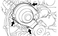
(a) Install the gasket to the belt cover. |
|
(b) Install the cover with the cap nut and 3 bolts.
Torque:
7.5 N·m {76 kgf·cm, 66in·lbf}
12.
CONNECT COMPRESSOR ASSEMBLY
![2007 MY LX470 [08/2006 - ]; AIR CONDITIONING: COMPRESSOR AND MAGNETIC CLUTCH: INSTALLATION+](../../../../stylegraphics/info.gif "2007 MY LX470 [08/2006 - ]; AIR CONDITIONING: COMPRESSOR AND MAGNETIC CLUTCH: INSTALLATION+")
13.
INSTALL GENERATOR ASSEMBLY
14.
INSTALL VANE PUMP ASSEMBLY
15.
INSTALL DRIVE BELT
16.
INSTALL RADIATOR ASSEMBLY
17.
CONNECT NO. 1 OIL COOLER OUTLET TUBE
18.
CONNECT NO. 1 OIL COOLER INLET TUBE
19.
CONNECT NO. 2 RADIATOR HOSE
20.
CONNECT NO. 1 RADIATOR HOSE
21. INSTALL AIR CLEANER ASSEMBLY
(a) Install the air cleaner assembly with the 3 bolts.
Torque:
5.0 N·m {51 kgf·cm, 44in·lbf}
(b) Connect the MAF meter connector and clamp to the air cleaner.
22.
INSTALL AIR CLEANER HOSE ASSEMBLY
23.
INSTALL V-BANK COVER
24. CONNECT CABLE TO NEGATIVE BATTERY TERMINAL
25. PERFORM INITIALIZATION
(a)
Perform initialization
.
NOTICE:
Certain systems need to be initialized after disconnecting and reconnecting the cable from the negative (-) battery terminal.
26.
ADD ENGINE COOLANT
27.
CHECK FOR ENGINE COOLANT LEAKS
28. INSTALL NO. 1 ENGINE UNDER COVER
(a) Install the engine under cover with the 5 bolts.
29. INSTALL ENGINE REAR UNDER COVER
(a) Install the engine under cover with the 8 bolts.

|

|