| Last Modified: 7-3-2017 | 6.8:8.0.40 | Doc ID: RM000000SMV00EX |
| Model Year Start: 2007 | Model: LX470 | Prod Date Range: [08/2006 - ] |
| Title: 2UZ-FE ENGINE MECHANICAL: CYLINDER HEAD: REMOVAL; 2007 MY LX470 [08/2006 - ] | ||
REMOVAL
1.
DISCHARGE FUEL SYSTEM PRESSURE
![2007 MY LX470 [08/2006 - ]; 2UZ-FE FUEL: FUEL INJECTOR: REMOVAL+](../../../../stylegraphics/info.gif "2007 MY LX470 [08/2006 - ]; 2UZ-FE FUEL: FUEL INJECTOR: REMOVAL+")
2. DISCONNECT CABLE FROM NEGATIVE BATTERY TERMINAL
CAUTION:
Wait at least 90 seconds after disconnecting the cable from the negative (-) battery terminal to prevent airbag activation.
3. DRAIN ENGINE OIL
(a) Remove the oil pan drain plug and drain the engine oil.
(b) Clean the oil pan drain plug and install a new gasket and the drain plug.
Torque:
39 N·m {398 kgf·cm, 29ft·lbf}
4. REMOVE TIMING BELT
(a)
Remove the timing belt
.
5.
DISCONNECT NO. 1 FUEL HOSE
6.
DISCONNECT NO. 2 FUEL HOSE
7.
REMOVE FRONT EXHAUST PIPE LH
8.
REMOVE FRONT EXHAUST PIPE RH
9.
REMOVE INTAKE MANIFOLD ASSEMBLY
10.
REMOVE AIR SWITCHING VALVE ASSEMBLY
11.
REMOVE AIR PUMP ASSEMBLY
12.
REMOVE CAMSHAFT POSITION SENSOR
13.
REMOVE VVT SENSOR (for Bank 1)
14.
REMOVE VVT SENSOR (for Bank 2)
15.
REMOVE KNOCK SENSOR
16.
REMOVE CAMSHAFT TIMING OIL CONTROL VALVE ASSEMBLY (for Bank 1)
17.
REMOVE CAMSHAFT TIMING OIL CONTROL VALVE ASSEMBLY (for Bank 2)
18.
REMOVE STARTER ASSEMBLY
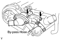
19. REMOVE WATER INLET HOUSING
(a) Disconnect the water by-pass hose from the water inlet housing.
|
(b) Remove the 2 bolts and inlet housing. |
|
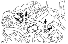
20. REMOVE FRONT WATER BY-PASS JOINT
(a) Disconnect the ECT sensor connector and by-pass hose.
|
(b) Remove the 4 nuts, water by-pass joint and 2 gaskets. |
|
21. DISCONNECT HEATER HOSE
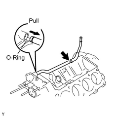
22. REMOVE WATER BY-PASS PIPE SUB ASSEMBLY
|
(a) Remove the bolt. |
|
(b) Pull out the water by-pass pipe.
(c) Remove the O-ring from the water by-pass pipe.
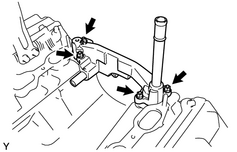
23. REMOVE REAR WATER BY-PASS JOINT
|
(a) Remove the 4 nuts and water by-pass joint. |
|
(b) Remove the 2 gaskets from the water by-pass joint.
24. REMOVE OIL DIPSTICK GUIDE WITH DIPSTICK
(a) Remove the bolt and dipstick guide with dipstick.
(b) Remove the O-ring.
25. REMOVE IGNITION COIL
(a) Remove the 8 bolts and 8 ignition coils.
26. REMOVE SPARK PLUG
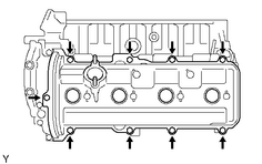
27. REMOVE CYLINDER HEAD COVER SUB-ASSEMBLY LH
|
(a) Remove the 9 bolts, 9 seal washers and cylinder head cover. |
|
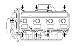
28. REMOVE CYLINDER HEAD COVER SUB-ASSEMBLY RH
|
(a) Remove the 9 bolts, 9 seal washers and cylinder head cover. |
|
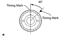
29. WORK FOR PISTON AND VALVE DAMAGE PREVENTION
|
(a) Turn the crankshaft timing pulley counterclockwise by 45° and match the timing mark with the illustrated position. HINT: When the No. 1 cylinder is positioned at 45° BTDC, the valve and piston do not interfere with each other even when the valve is fully open. NOTICE: Be sure to match the cut part by turning it counterclockwise. |
|
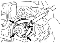
30. REMOVE CAMSHAFT TIMING PULLEY LH
|
(a) Hold the camshaft timing pulley with SST, loosen the 4 bolts of the timing pulley. SST: 09960-10010 09962-01000 09963-01000 |
|
(b) Remove the timing pulley.
31. REMOVE CAMSHAFT TIMING PULLEY RH
|
(a) Hold the camshaft timing pulley with SST, loosen the 4 bolts of the timing pulley. SST: 09960-10010 09962-01000 09963-01000 |
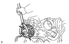
|
(b) Remove the timing pulley.
32. REMOVE REAR NO. 2 TIMING BELT PLATE LH
(a) Remove the 2 bolts and No. 2 timing belt plate.
33. REMOVE REAR TIMING BELT PLATE LH
(a) Remove the bolt and timing belt plate.
34. REMOVE REAR NO. 2 TIMING BELT PLATE RH
(a) Remove the 2 bolts and No. 2 timing belt plate.
35. REMOVE REAR TIMING BELT PLATE RH
(a) Remove the bolt, stud bolt and timing belt plate.
36. REMOVE CAMSHAFT (for Bank 1)
NOTICE:
Since the thrust clearance of the camshaft is small, the camshaft must be kept level while it is being removed. If the camshaft is not kept level, the portion of the cylinder head receiving the shaft thrust may crack or be damaged, causing the camshaft to seize or break. To avoid this, the following steps should be carried out.
|
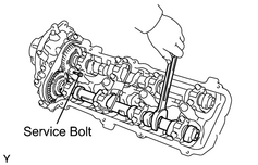
(a) Bring the service bolt hole of the sub-gear upward by turning the hexagon head portion of the No. 4 camshaft with a wrench. |
|
(b) Secure the sub-gear to the main gear with a service bolt.
Recommended service bolt:
|
Thread Diameter |
Thread Pinch |
Bolt Length |
|---|---|---|
|
6 mm |
1.0 mm |
16 to 20 mm (0.63 to 0.79 in.) |
HINT:
When removing the camshaft, make sure that the torsional spring force of the sub-gear has been eliminated by the above operation.
|
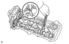
(c) Set a wrench to the hexagon head portion of the No. 4 camshaft. Turn the wrench so that the timing marks (2 dot marks each) on the camshaft drive and driven main gears are aligned, as shown in the illustration. |
|
|
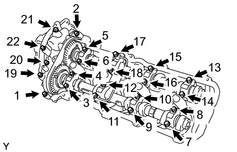
(d) Uniformly loosen the 22 bearing cap bolts in several passes in the sequence shown in the illustration. |
|
(e) Remove the 22 bearing cap bolts, 4 seal washers, oil feed pipe, 9 bearing caps, camshaft housing plug, oil control valve filter and the No. 3 and No. 4 camshafts.
NOTICE:
- Do not forcibly pry the camshaft with a tool.
- Do not damage the reception part of the thrust on the cylinder head side.
37. REMOVE CAMSHAFT (for Bank 2)
NOTICE:
Since the thrust clearance of the camshaft is small, the camshaft must be kept level while it is being removed. If the camshaft is not kept level, the portion of the cylinder head receiving the shaft thrust may crack or be damaged, causing the camshaft to seize or break. To avoid this, the following steps should be carried out.
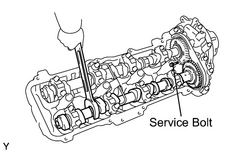
|
(a) Bring the service bolt hole of the sub-gear upward by turning the hexagon head portion of the No. 2 camshaft with a wrench. |
|
(b) Secure the sub-gear to the main gear with a service bolt.
Recommended service bolt:
|
Thread diameter |
Thread pinch |
Bolt length |
|---|---|---|
|
6 mm |
1.0 mm |
16 to 20 mm (0.63 to 0.79 in.) |
HINT:
When removing the camshaft, make sure that the torsional spring force of the sub-gear has been eliminated by the above operation.
|
(c) Set a wrench to the hexagon head portion of the No. 2 camshaft. Turn the wrench so that the timing mark (1 dot mark) on the camshaft main gear is moved approximately 10°, as shown in the illustration. |
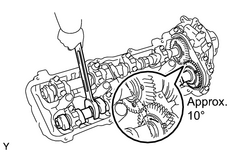
|
|
(d) Uniformly loosen the 22 bearing cap bolts in several passes in the sequence shown in the illustration. |
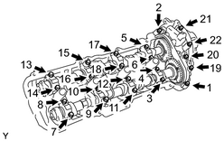
|
(e) Remove the 22 bearing cap bolts, 4 seal washers, oil feed pipe, 9 bearing caps, camshaft housing plug, oil control valve filter and the No. 1 and No. 2 camshafts.
NOTICE:
- Do not forcibly pry the camshaft with a tool.
- Do not damage the reception part of the thrust on the cylinder head side.
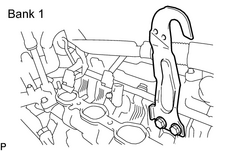
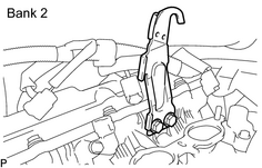
38. REMOVE NO. 1 ENGINE HANGER
|
(a) Remove the 2 bolts and engine hanger. |
|
39. REMOVE NO. 2 ENGINE HANGER
|
(a) Remove the 2 bolts and engine hanger. |
|
40. REMOVE CYLINDER HEAD LH
|
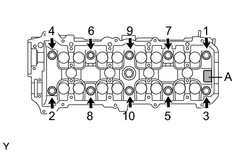
(a) Uniformly loosen the 10 cylinder head bolts on the cylinder head in several passes, in the sequence shown in the illustration. Remove the 10 cylinder head bolts and plate washers. NOTICE:
|
|
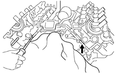
(b) Lift the cylinder head from the ring pins on the cylinder block, and place the cylinder head on wooden blocks on a bench.
|
(c) Remove the cylinder head together with the exhaust manifold. NOTICE:
HINT: If the cylinder head cannot be lifted easily, pry between the cylinder head and cylinder block with a screwdriver. |
|
41. REMOVE CYLINDER HEAD GASKET LH
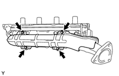
42. REMOVE NO. 2 EXHAUST MANIFOLD HEAT INSULATOR
|
(a) Remove the 4 bolts and heat insulator. |
|
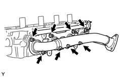
43. REMOVE EXHAUST MANIFOLD SUB-ASSEMBLY LH
|
(a) Remove the 8 nuts, exhaust manifold and gasket. |
|
44. REMOVE CYLINDER HEAD RH
|
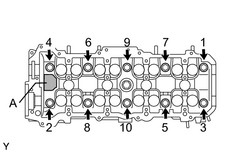
(a) Uniformly loosen the 10 cylinder head bolts on the cylinder head in several passes, in the sequence shown in the illustration. Remove the 10 cylinder head bolts and plate washers. NOTICE:
|
|
(b) Lift the cylinder head from the ring pins on the cylinder block, and place the cylinder head on wooden blocks on a bench.
|
(c) Remove the cylinder head together with the exhaust manifold. NOTICE:
HINT: If the cylinder head cannot be lifted easily, pry between the cylinder head and cylinder block with a screwdriver. |
|
45. REMOVE CYLINDER HEAD GASKET RH
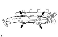
46. REMOVE NO. 1 EXHAUST MANIFOLD HEAT INSULATOR
|
(a) Remove the 4 bolts and heat insulator. |
|
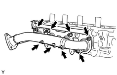
47. REMOVE EXHAUST MANIFOLD SUB-ASSEMBLY RH
|
(a) Remove the 8 nuts, exhaust manifold and gasket. |
|

|

|