- ETCS
- Air induction system
- Ventilation hose connection
- ECM
| Last Modified: 7-3-2017 | 6.8:8.0.40 | Doc ID: RM000000T8M02TX |
| Model Year Start: 2007 | Model: LX470 | Prod Date Range: [08/2006 - ] |
| Title: 2UZ-FE ENGINE CONTROL SYSTEM: SFI SYSTEM: P0505; Idle Control System Malfunction; 2007 MY LX470 [08/2006 - ] | ||
|
DTC |
P0505 |
Idle Control System Malfunction |
DESCRIPTION
The idle speed is controlled by the Electronic Throttle Control System (ETCS). The ETCS is comprised of: 1) one valve type throttle body; 2) the throttle actuator, which operates the throttle valve; 3) the throttle position sensor, which detects the opening angle of the throttle valve; 4) the accelerator pedal position sensor, which detects the accelerator pedal position; and 5) the ECM, which controls the ETCS. Based on the target idle speed, the ECM controls the throttle actuator to provide the proper throttle valve opening angle.
|
DTC No. |
DTC Detection Condition |
Trouble Area |
|---|---|---|
|
P0505 |
Idle speed continues to vary greatly from target speed (2 trip detection logic) |
|
MONITOR DESCRIPTION
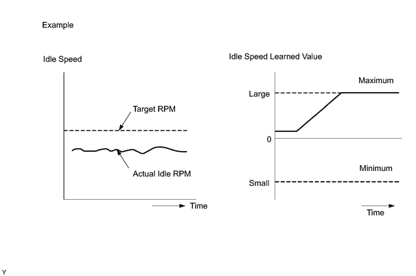
The ECM detects idle speed and idle air flow amount for Idle Speed Control (ISC). The ECM concludes that the ISC is malfunctioning if: 1) the learned value of the ISC remains at the maximum or minimum 5 times or more during a drive cycle, and 2) while driving at 10 km/h (6 mph) or more, the actual idle RPM varies from the target RPM by between 100 to 200 RPM 5 times or more during a drive cycle.
Example:
If the actual idle RPM varies from the target idle RPM by more than 200 rpm* 5 times during a drive cycle, the ECM will turn on the MIL and a DTC is set.
HINT:
*: RPM threshold varies with engine load.
MONITOR STRATEGY
|
Related DTCs |
P0505: IAC functional check P0505: IAC range check |
|
Required Sensors/Components (Main) |
ETCS |
|
Required Sensors/Components (Related) |
Crankshaft position sensor, ECT sensor, Vehicle speed sensor |
|
Frequency of Operation |
Continuous |
|
Duration |
10 minutes: IAC functional check |
|
MIL Operation |
2 drive cycles: IAC functional check |
|
Sequence of Operation |
None |
TYPICAL ENABLING CONDITIONS
|
Monitor will run whenever these DTCs are not present |
None |
|
Engine |
Running |
TYPICAL MALFUNCTION THRESHOLDS
|
1. Frequency that both of following conditions (a) and (b) are met |
5 times or more |
|
(a) Engine RPM - Target engine RPM (A/C OFF and NSW OFF) |
Less than -100 rpm, or more than 150 rpm |
|
(b) Vehicle condition |
Stop after vehicle was driven at 10 km/h (6 mph) or more |
|
2. Frequency that both of following conditions (a) and (b) are met |
Once |
|
(a) Engine RPM - Target engine RPM (A/C OFF and NSW OFF) |
Less than -100 rpm, or more than 150 rpm |
|
(b) IAC flow rate learning value |
2.48 L/sec or less. or 11 L/sec |
INSPECTION PROCEDURE
HINT:
- The detection of DTC P0505 may also be caused by: 1) the floor carpet overlapping onto the accelerator pedal, causing the accelerator pedal to be slightly depressed (throttle position to be slightly open); or 2) the accelerator pedal not being fully released.
- Read freeze frame data using the intelligent tester. Freeze frame data records the engine conditions when malfunctions are detected. When troubleshooting, freeze frame data can help determine if the vehicle was running or stopped, if the engine was warmed up or not, if the air fuel ratio was lean or rich, and other data from the time the malfunction occurred.
PROCEDURE
|
1. |
CHECK OTHER DTC OUTPUT (IN ADDITION TO DTC P0505) |
(a) Connect the intelligent tester to the CAN VIM. Then connect the CAN VIM to the DLC3.
(b) Turn the ignition switch ON.
(c) Enter the following menus: DIAGNOSIS / ENHANCED OBD II / DTC INFO / CURRENT CODES.
(d) Read the DTCs.
HINT:
If any other codes besides P0101 are output, perform troubleshooting for those DTCs first.
|
Display (DTC output) |
Proceed to |
|---|---|
|
P0505 |
A |
|
P0505 and other DTCs |
B |
HINT:
If any DTCs other than P0505 are output, troubleshoot those DTCs first.
| B |

|
|

|
2. |
CHECK CONNECTION OF VENTILATION HOSE |
OK:
Ventilation hose is connected correctly and is not damaged.
| NG |
|
|
|
3. |
CHECK AIR INDUCTION SYSTEM |
(a) Check for vacuum leaks in the air induction system.
OK:
No leakage from air induction system.
| NG |
|
|
|
4. |
CHECK THROTTLE VALVE |
(a) Check the throttle valve condition.
| NG |
|
| OK |
|

|

|