-
Conditions (a), (b) and (c) continue for 0.5 sec or more:
- (a) Ignition switch ON
- (b) Brake pedal released
- (c) STP signal is OFF when the ST1- signal is OFF
| Last Modified: 7-3-2017 | 6.8:8.0.40 | Doc ID: RM000000T8O00ZX |
| Model Year Start: 2007 | Model: LX470 | Prod Date Range: [08/2006 - ] |
| Title: 2UZ-FE ENGINE CONTROL SYSTEM: SFI SYSTEM: P0504; Brake Switch "A" / "B" Correlation; 2007 MY LX470 [08/2006 - ] | ||
|
DTC |
P0504 |
Brake Switch "A" / "B" Correlation |
DESCRIPTION
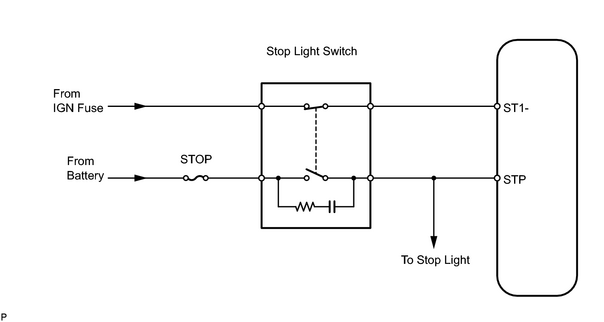
In addition to turning on the stop lights, the stop light switch signals are used for a variety of engine, transmission and suspension functions. The stop light switch is designed with 2 complementary signal outputs, STP and ST1-. The ECM analyzes these signal outputs to detect malfunctions in the stop light switch.
HINT:
The normal signal conditions are as shown in the table below.
|
Signal (ECM Terminal) |
Brake Pedal Released |
In Transition |
Brake Pedal Depressed |
|---|---|---|---|
|
STP |
OFF |
ON |
ON |
|
ST1- |
ON |
ON |
OFF |
- [OFF] denotes ground potential.
- [ON] denotes battery potential (+B).
- On the intelligent tester, both the Data List items STOP LIGHT SW and ST1 are ON when the brake pedal is depressed because the characteristics of ST1 indication are the opposite of the STOP LIGHT SW indication.
|
DTC No. |
DTC Detection Condition |
Trouble Area |
|---|---|---|
|
P0504 |
|
|
WIRING DIAGRAM
INSPECTION PROCEDURE
HINT:
- Read freeze frame data using the intelligent tester. Freeze frame data records the engine conditions when malfunctions are detected. When troubleshooting, freeze frame data can help determine if the vehicle was running or stopped, if the engine was warmed up or not, if the air fuel ratio was lean or rich, and other data from the time the malfunction occurred.
-
Stop light switch conditions can be checked using the intelligent tester.
- Connect the intelligent tester to the DLC3.
- Turn the ignition switch on.
- Turn the tester on.
- Enter the following menus: DIAGNOSIS / ENHANCED OBD II / DATA LIST / PRIMARY / STOP LIGHT SW and ST1.
-
Check the Data List indication when the brake pedal is depressed and released.
Brake Pedal Operation
STOP LIGHT SW
ST1
Depressed
ON
ON
Released
OFF
OFF
PROCEDURE
|
1. |
CHECK OPERATION OF STOP LIGHT |
(a) Check if the stop lights turn on and off normally when the brake pedal is depressed and released.
OK :
Stop light turns ON when brake pedal is depressed.
| NG |

|
|

|
2. |
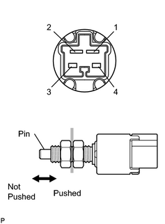
INSPECT STOP LIGHT SWITCH ASSEMBLY |
|
(a) Remove the stop light switch assembly. (b) Measure the resistance of the stop light switch assembly. Standard resistance:
|
|
| NG |
|
|
|
3. |
READ VALUE USING INTELLIGENT TESTER (STP SIGNAL AND ST1- VOLTAGE) |
|
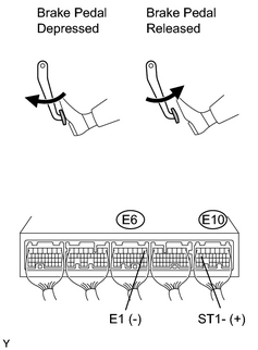
(a) Connect the intelligent tester to the CAN VIM. Then connect the CAN VIM to the DLC3. (b) Turn the ignition switch ON. (c) Enter the following menus: DIAGNOSIS / ENHANCED OBD II / DATA LIST / PRIMARY / STOP LIGHT SW. (d) Confirm the stop light switch status when the brake pedal is depressed and released. OK:
(e) Measure the voltage of the ECM when the brake pedal is depressed and released. Standard voltage:
|
|
| OK |
|
|
|
4. |
CHECK HARNESS AND CONNECTOR (STOP LIGHT SWITCH - ECM) |
(a)
Check harness and connector
![2007 MY LX470 [08/2006 - ]; INTRODUCTION: HOW TO TROUBLESHOOT ECU CONTROLLED SYSTEMS: ELECTRONIC CIRCUIT INSPECTION PROCEDURE](../../../../stylegraphics/info.gif "2007 MY LX470 [08/2006 - ]; INTRODUCTION: HOW TO TROUBLESHOOT ECU CONTROLLED SYSTEMS: ELECTRONIC CIRCUIT INSPECTION PROCEDURE") .
.
| NG |
|
| OK |
|

|

|