- Open or short in fuel pump relay circuit
- Fuel pump relay
- ECM
| Last Modified: 7-3-2017 | 6.8:8.0.40 | Doc ID: RM000000T8X01UX |
| Model Year Start: 2007 | Model: LX470 | Prod Date Range: [08/2006 - ] |
| Title: 2UZ-FE ENGINE CONTROL SYSTEM: SFI SYSTEM: P0230; Fuel Pump Primary Circuit; 2007 MY LX470 [08/2006 - ] | ||
|
DTC |
P0230 |
Fuel Pump Primary Circuit |
DESCRIPTION
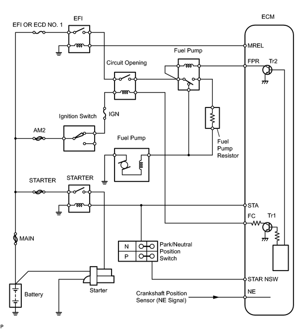
In the diagram below, when the engine is cranked, current flows from terminal STAR NSW of the ECM to the starter relay coil and also current flows to terminal STA of the ECM (STA signal).
When the STA signal and NE signal are input to the ECM, the Tr1 (power transistor 1) is turned ON, current flows to the coil of the circuit opening relay (Marking: C/OPN), the relay switches on, power is supplied to the fuel pump, and the fuel pump operates.
While the NE signal is generated (engine running), the ECM keeps the Tr1 ON (circuit opening relay ON) and the fuel pump also keeps operating.
The fuel pump speed is controlled at two levels (high speed or low speed) by the engine condition (starting, light load, heavy load). When the engine starts (STA ON), the Tr2 (power transistor 2) in the ECM is OFF, so the fuel pump relay (Marking: F/PUMP) closes and battery positive voltage is applied directly to the fuel pump. The fuel pump operates at high speed.
After the engine starts during idling or light loads, since the Tr2 goes ON, power is supplied to the fuel pump via the fuel pump resistor. The fuel pump operates at low speed.
|
DTC No. |
DTC Detection Condition |
Trouble Area |
|---|---|---|
|
P0230 |
Open or short in fuel pump relay circuit for 1 second or more (1 trip detection logic) |
|
WIRING DIAGRAM
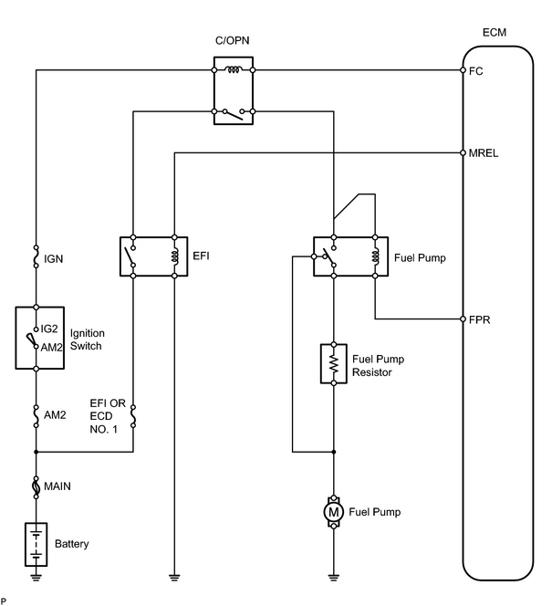
HINT:
This troubleshooting procedure is based on the premise that the engine is started. If the engine is not started, proceed to the problem symptoms table
![2007 MY LX470 [08/2006 - ]; 2UZ-FE ENGINE CONTROL SYSTEM: SFI SYSTEM: PROBLEM SYMPTOMS TABLE](../../../../stylegraphics/info.gif "2007 MY LX470 [08/2006 - ]; 2UZ-FE ENGINE CONTROL SYSTEM: SFI SYSTEM: PROBLEM SYMPTOMS TABLE") .
.
INSPECTION PROCEDURE
PROCEDURE
|
1. |
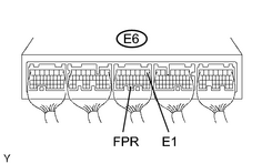
CHECK ECM (FPR VOLTAGE) |
|
(a) Measure the voltage of the ECM connectors. Standard voltage:
|
|
| NG |

|
|

|
2. |
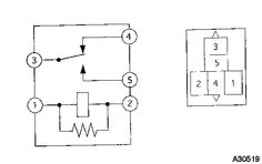
INSPECT FUEL PUMP RELAY (Marking: F/PUMP) |
|
(a) Remove the fuel pump relay from the engine room relay block. (b) Measure the resistance of the fuel pump relay. Standard resistance:
|
|
| NG |
|
|
|
3. |
CHECK HARNESS AND CONNECTOR (FUEL PUMP RELAY - ECM) |
(a)
Check harness and connector
.
| NG |
|
| OK |
|

|

|