- Vehicle speed is greater than 20 km/h (12 mph)
- Engine RPM is greater than 1,000 rpm
- ECM detects STA
| Last Modified: 7-3-2017 | 6.8:8.0.40 | Doc ID: RM000000TA0038X |
| Model Year Start: 2007 | Model: LX470 | Prod Date Range: [08/2006 - ] |
| Title: 2UZ-FE ENGINE CONTROL SYSTEM: SFI SYSTEM: P0617; Starter Relay Circuit High; 2007 MY LX470 [08/2006 - ] | ||
|
DTC |
P0617 |
Starter Relay Circuit High |
DESCRIPTION
HINT:
Refer to cranking holding function circuit
![2007 MY LX470 [08/2006 - ]; 2UZ-FE ENGINE CONTROL SYSTEM: SFI SYSTEM: Cranking Holding Function Circuit+](../../../../stylegraphics/info.gif "2007 MY LX470 [08/2006 - ]; 2UZ-FE ENGINE CONTROL SYSTEM: SFI SYSTEM: Cranking Holding Function Circuit+") .
.
If the vehicle is being driven and the ECM detects the starter control signal (STA), the ECM concludes that the starter control circuit is malfunctioning. The ECM will turn on the MIL and a DTC is set.
|
DTC No. |
DTC Detection Condition |
Trouble Area |
|---|---|---|
|
P0617 |
The following conditions are met for 20 seconds: |
|
MONITOR STRATEGY
|
Related DTCs |
P0617: Starter signal |
|
Required Sensors/Components (Main) |
STARTER relay, PNP switch, Ignition switch |
|
Required Sensors/Components (Related) |
Vehicle speed sensor, Crankshaft position sensor |
|
Frequency of Operation |
Continuous |
|
Duration |
20 seconds |
|
MIL Operation |
Immediate |
|
Sequence of Operation |
None |
TYPICAL ENABLING CONDITIONS
|
Monitor runs whenever these DTCs are not present |
None |
|
Battery voltage |
10.5 V or more |
|
Vehicle speed |
20 km/h (12.5 mph) or more |
|
Engine rpm |
1,000 rpm or more |
TYPICAL MALFUNCTION THRESHOLDS
|
Starter signal |
ON |
WIRING DIAGRAM
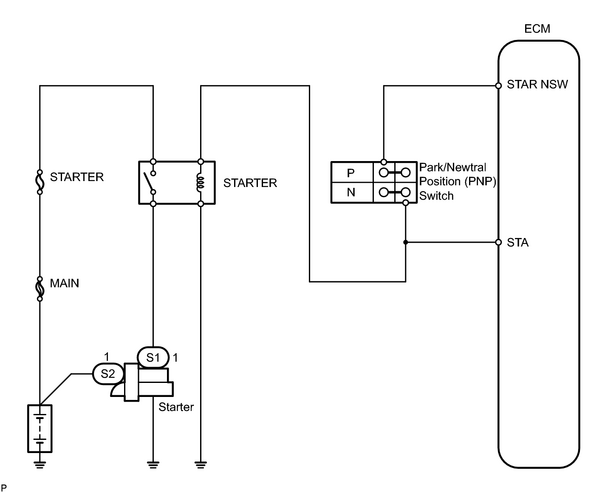
INSPECTION PROCEDURE
HINT:
-
The following troubleshooting flowchart is based on the premise that the engine is cranked normally.
If the engine will not crank, proceed to the problem symptoms table
.
- Read freeze frame data using the intelligent tester. Freeze frame data records the engine conditions when malfunctions are detected. When troubleshooting, freeze frame data can help determine if the vehicle was running or stopped, if the engine was warmed up or not, if the air fuel ratio was lean or rich, and other data from the time the malfunction occurred.
PROCEDURE
|
1. |
READ VALUE USING INTELLIGENT TESTER (STARTER SIGNAL) |
(a) Connect the intelligent tester to the CAN VIM. Then connect the CAN VIM to the DLC3.
(b) Turn the ignition switch ON and turn the intelligent tester ON.
(c) Enter the following menus: DIAGNOSIS / ENHANCED OBD II / DATA LIST / PRIMARY / STARTER SIG.
(d) Confirm the starter signal status when the ignition switch is operated.
OK:
|
Ignition Switch Position |
STARTER SIG |
|---|---|
|
ON |
OFF |
|
Start |
ON |
| OK |

|
|

|
2. |
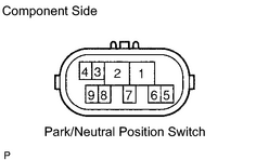
INSPECT PARK / NEUTRAL POSITION SWITCH |
|
(a) Move the shift lever to the P or N position. (b) Disconnect the P1 Park/Neutral Position (PNP) switch connector. (c) Measure the resistance of the PNP switch. Standard resistance:
|
|
| NG |
|
REPLACE PARK / NEUTRAL POSITION SWITCH (GO TO STEP 5 AFTER THE REPLACEMENT) |
|
|
3. |
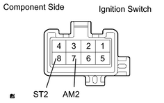
INSPECT IGNITION SWITCH ASSEMBLY |
|
(a) Disconnect the I18 ignition switch connector. (b) Measure the resistance between the connector terminals shown in the chart below. Standard resistance:
|
|
| NG |
|
REPLACE IGNITION SWITCH ASSEMBLY (GO TO STEP 5 AFTER THE REPLACEMENT) |
|
|
4. |
READ VALUE USING INTELLIGENT TESTER (STARTER SIGNAL) |
(a) Connect the intelligent tester to the CAN VIM. Then connect the CAN VIM to the DLC3.
(b) Turn the ignition switch ON and turn the tester ON.
(c) On the intelligent tester, enter the following menus: DIAGNOSIS / ENHANCED OBD II / DATA LIST / ALL / STARTER SIG.
(d) Read the values.
|
Ignition Switch Position |
STARTER SIG |
|---|---|
|
ON |
OFF |
|
START |
ON |
| NG |
|
|
|
5. |
CHECK IF DTC OUTPUT REOCCURS |
(a) Connect the intelligent tester to the CAN VIM. Then connect the CAN VIM to the DLC3.
(b) Turn the ignition switch ON and turn the tester ON.
(c) To erase DTC, enter the following menus: DIAGNOSIS / ENHANCED OBD II / DTC INFO / CLEAR CODE; and press YES.
(d) Drive the vehicle more than 40 km/h (25 mph) for 20 seconds or more.
(e) Check if DTC output reoccurs.
|
Display (DTC output) |
Proceed to |
|---|---|
|
P0617 |
A |
|
No output |
B |
| B |
|
| A |
|

|

|