| Last Modified: 7-3-2017 | 6.8:8.0.40 | Doc ID: RM000000TMK00WX |
| Model Year Start: 2007 | Model: LX470 | Prod Date Range: [08/2006 - ] |
| Title: 2UZ-FE ENGINE CONTROL SYSTEM: SFI SYSTEM: Fuel Pump Control Circuit; 2007 MY LX470 [08/2006 - ] | ||
|
Fuel Pump Control Circuit |
DESCRIPTION
Refer to DTC P0230
![2007 MY LX470 [08/2006 - ]; 2UZ-FE ENGINE CONTROL SYSTEM: SFI SYSTEM: P0230; Fuel Pump Primary Circuit+](../../../../stylegraphics/info.gif "2007 MY LX470 [08/2006 - ]; 2UZ-FE ENGINE CONTROL SYSTEM: SFI SYSTEM: P0230; Fuel Pump Primary Circuit+") .
.
WIRING DIAGRAM
Refer to DTC P0230
.
INSPECTION PROCEDURE
PROCEDURE
|
1. |
CHECK FUEL PUMP OPERATION |
(a) Check if there is pressure in the fuel inlet hose.
HINT:
If there is fuel pressure, you will hear the sound of fuel flowing.
| OK |

|
|

|
2. |
PERFORM ACTIVE TEST USING INTELLIGENT TESTER (OPERATE CIRCUIT OPENING RELAY) |
(a) Connect the intelligent tester to the CAN VIM. Then connect the CAN VIM to the DLC3.
(b) Turn the ignition switch ON and turn the intelligent tester ON.
(c) Enter the following menus: DIAGNOSIS / ENHANCED OBD II / ACTIVE TEST / FUEL PUMP / SPD.
(d) Check the relay operation when it is operated by the intelligent tester.
Standard:
Operating sound can be heard from the relay.
| OK |
|
|
|
3. |
INSPECT CIRCUIT OPENING RELAY (Marking: C/OPN) |
|
(a) Remove the circuit opening relay from the engine room relay block. (b) Measure the resistance of the circuit opening relay. Standard resistance:
(c) Reinstall the circuit opening relay. |
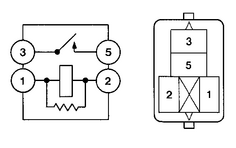
|
| NG |
|
|
|
4. |
INSPECT ECM (FC VOLTAGE) |
|
(a) Turn the ignition switch ON. (b) Measure the voltage of the E6 and E10 ECM connectors. Standard voltage:
|
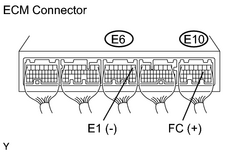
|
| OK |
|
| NG |
|
CHECK AND REPAIR HARNESS OR CONNECTOR (ECM - CIRCUIT OPENING RELAY, CIRCUIT OPENING RELAY - IGNITION SWITCH) |
|
5. |
CHECK ECM POWER SOURCE CIRCUIT |
(a)
Check ECM Power Source Circuit
.
| NG |
|
|
|
6. |
INSPECT FUEL PUMP RELAY (Marking: F/PUMP) |
|
(a) Remove the fuel pump relay from the engine room relay block. (b) Measure the resistance of the fuel pump relay. Standard resistance:
(c) Reinstall the fuel pump relay. |
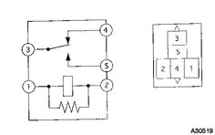
|
| NG |
|
|
|
7. |
INSPECT FUEL PUMP |
|
(a) Inspect fuel pump resistance. (1) Disconnect the F13 fuel pump connector. (2) Measure the resistance of the fuel pump. Standard resistance:
(3) Reconnect the fuel pump connector. (b) Inspect fuel pump operation. (1) Apply battery voltage to F13-4 (+) and F13-5 (-) terminals. Check that the pump operates. NOTICE:
|
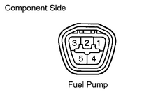
|
| NG |
|
|
|
8. |
CHECK HARNESS AND CONNECTOR (FUEL PUMP - FUEL PUMP RELAY, FUEL PUMP - BODY GROUND) |
(a)
Check harness and connector
.
| NG |
|
|
|
9. |
CHECK HARNESS AND CONNECTOR (CIRCUIT OPENING RELAY - FUEL PUMP RELAY) |
(a)
Check harness and connector
.
| NG |
|
| OK |
|
CHECK AND REPAIR HARNESS OR CONNECTOR (EFI RELAY - CIRCUIT OPENING RELAY) |
|
10. |
INSPECT FUEL PUMP RELAY (Marking: F/PUMP) |
|
(a) Remove the fuel pump relay from the engine room relay block. (b) Measure the resistance of the fuel pump relay. Standard resistance:
(c) Reinstall the fuel pump relay. |
|
| NG |
|
|
|
11. |
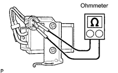
INSPECT FUEL PUMP RESISTOR (RESISTANCE) |
|
(a) Inspect the fuel pump resistor resistance. (1) Measure the resistance of the terminals. Resistance: 0.94 to 1.0 Ω at 20°C (68°F) |
|
| NG |
|
|
|
12. |
CHECK HARNESS AND CONNECTOR (FUEL PUMP RELAY - FUEL PUMP RESISTOR, FUEL PUMP RESISTOR - FUEL PUMP) |
(a)
Check harness and connector
.
| OK |
|
PROCEED TO NEXT CIRCUIT INSPECTION SHOWN IN PROBLEM SYMPTOMS TABLE |
| NG |
|

|

|