| Last Modified: 7-3-2017 | 6.8:8.0.40 | Doc ID: RM000000TMR00RX |
| Model Year Start: 2007 | Model: LX470 | Prod Date Range: [08/2006 - ] |
| Title: 2UZ-FE ENGINE CONTROL SYSTEM: SFI SYSTEM: ECM Power Source Circuit; 2007 MY LX470 [08/2006 - ] | ||
|
ECM Power Source Circuit |
DESCRIPTION
When the ignition switch is turned ON, the positive battery voltage is applied to terminal IGSW of the ECM and the EFI relay (Marking: EFI OR ECD) control circuit in the ECM sends a signal to terminal MREL of the ECM switching on the EFI relay.
This signal causes current to flow to the coil, closing the contacts of the EFI relay and supplying power to terminal +B of the ECM.
If the ignition switch is turned OFF, the ECM holds the EFI relay for a maximum of 2 seconds to allow for the initial setting of the throttle valve.
WIRING DIAGRAM
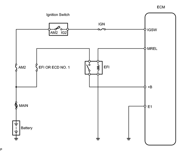
INSPECTION PROCEDURE
PROCEDURE
|
1. |
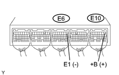
CHECK ECM (+B VOLTAGE) |
|
(a) Turn the ignition switch ON. (b) Measure the voltage of the ECM connectors. Standard voltage:
|
|
| OK |

|
PROCEED TO NEXT CIRCUIT INSPECTION SHOWN ON PROBLEM SYMPTOMS TABLE |
|

|
2. |
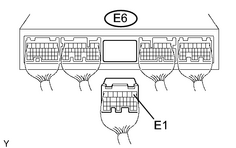
CHECK HARNESS AND CONNECTOR (ECM - BODY GROUND) |
|
(a) Disconnect the E6 ECM connector. (b) Measure the resistance of the wire harness side connector. Standard resistance:
|
|
| NG |
|
|
|
3. |
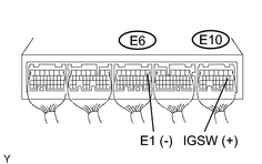
CHECK ECM (IGSW VOLTAGE) |
|
(a) Turn the ignition switch ON. (b) Measure the voltage of the ECM connectors. Standard voltage:
|
|
| OK |
|
|
|
4. |
INSPECT FUSE (IGN) |
|
(a) Remove the IGN fuse from the cowl side junction block RH. (b) Measure the resistance of the IGN fuse. Standard resistance: Below 1 Ω |
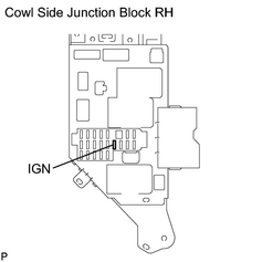
|
| NG |
|
CHECK FOR SHORT IN ALL HARNESSES AND COMPONENTS CONNECTED TO IGN FUSE, AND REPLACE IGN FUSE |
|
|
5. |
INSPECT IGNITION SWITCH ASSEMBLY |
|
(a) Remove the I18 ignition switch connector. (b) Measure the resistance of the ignition switch. Standard resistance:
|
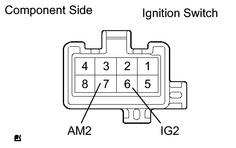
|
| NG |
|
| OK |
|
REPAIR OR REPLACE HARNESS OR CONNECTOR (BATTERY - IGNITION SWITCH, IGNITION SWITCH - ECM) |
|
6. |
CHECK ECM (MREL VOLTAGE) |
|
(a) Turn the ignition switch ON. (b) Measure the voltage of the ECM connectors. Standard voltage:
|
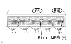
|
| NG |
|
|
|
7. |
INSPECT FUSE (EFI OR ECD NO. 1) |
|
(a) Remove the EFI OR ECD NO. 1 fuse from the engine room junction block. (b) Measure the resistance of the EFI OR ECD NO. 1 fuse. Standard resistance: Below 1 Ω |
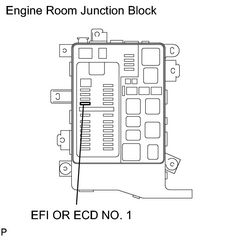
|
| NG |
|
CHECK FOR SHORT IN ALL HARNESSES AND COMPONENTS CONNECTED TO EFI OR ECD NO. 1 FUSE, AND REPLACE EFI OR ECD FUSE |
|
|
8. |
INSPECT EFI RELAY (Marking: EFI OR ECD) |
|
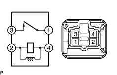
(a) Remove the EFI relay from the engine room relay block. (b) Measure the resistance of the EFI relay. Standard resistance:
|
|
| NG |
|
|
|
9. |
CHECK HARNESS AND CONNECTOR (EFI RELAY - ECM, EFI RELAY - BODY GROUND) |
(a)
Check harness and connector
![2007 MY LX470 [08/2006 - ]; INTRODUCTION: HOW TO TROUBLESHOOT ECU CONTROLLED SYSTEMS: ELECTRONIC CIRCUIT INSPECTION PROCEDURE](../../../../stylegraphics/info.gif "2007 MY LX470 [08/2006 - ]; INTRODUCTION: HOW TO TROUBLESHOOT ECU CONTROLLED SYSTEMS: ELECTRONIC CIRCUIT INSPECTION PROCEDURE") .
.
| OK |
|
| NG |
|
CHECK AND REPLACE HARNESS OR CONNECTOR (TERMINAL +B OF ECM - POSITIVE BATTERY TERMINAL) |

|

|