- Air induction system
- Injector blockage
- Mass Air Flow (MAF) meter
- Engine Coolant Temperature (ECT) sensor
- Fuel pressure
- Gas leakage in exhaust system
- Open or short in Air Fuel Ratio (A/F) sensor (bank 1, 2 sensor 1) circuit
- Air Fuel Ratio (A/F) sensor (bank 1, 2 sensor 1)
- Air Fuel Ratio (A/F) sensor heater (bank 1, 2 sensor 1)
- A/F relay
- A/F sensor heater and A/F relay circuit
- Ventilation valve and hose
- Ventilation hose connection
- ECM
| Last Modified: 7-3-2017 | 6.8:8.0.40 | Doc ID: RM000000TV800UX |
| Model Year Start: 2007 | Model: LX470 | Prod Date Range: [08/2006 - ] |
| Title: 2UZ-FE ENGINE CONTROL SYSTEM: SFI SYSTEM: P0171,P0172,P0174,P0175; System Too Lean (Bank 1); 2007 MY LX470 [08/2006 - ] | ||
|
DTC |
P0171 |
System Too Lean (Bank 1) |
|
DTC |
P0172 |
System Too Rich (Bank 1) |
|
DTC |
P0174 |
System Too Lean (Bank 2) |
|
DTC |
P0175 |
System Too Rich (Bank 2) |
DESCRIPTION
The fuel trim is related to the feedback compensation value, not to the basic injection time. The fuel trim consists of both the short-term and the long-term fuel trims.
The short-term fuel trim is fuel compensation that is used to constantly maintain the air fuel ratio at stoichiometric levels. The signal from the Air Fuel Ratio (A/F) sensor indicates whether the air fuel ratio is rich or lean compared to the stoichiometric ratio. This triggers a reduction in the fuel injection volume if the air fuel ratio is rich and an increase in the fuel injection volume if it is lean.
Factors such as individual engine differences, wear over time and changes in operating environment cause short-term fuel trim to vary from the central value. The long-term fuel trim, which controls overall fuel compensation, compensates for long-term deviations in the fuel trim from the central value caused by the short-term fuel trim compensation.
If both the short-term and long-term fuel trims are lean or rich beyond predetermined values, it is interpreted as a malfunction, and the ECM illuminates the MIL and sets a DTC.
|
DTC No. |
DTC Detection Condition |
Trouble Area |
|---|---|---|
|
P0171 P0174 |
When air fuel ratio feedback is stable after warming up engine, fuel trim is considerably in error on LEAN side (2 trip detection logic) |
|
|
P0172 P0175 |
When air fuel ratio feedback is stable after warming up engine, fuel trim is considerably in error on RICH side (2 trip detection logic) |
|
HINT:
- When DTC P0171 or P0174 is recorded, the actual air fuel ratio is on the LEAN side. When DTC P0172 or P0175 is recorded, the actual air fuel ratio is on the RICH side.
- If the vehicle runs out of fuel, the air fuel ratio is LEAN and DTC P0171 or P0174 may be recorded. The MIL is then illuminated.
- If the total of the short-term fuel trim value and long-term fuel trim value is within the malfunction threshold (and ECT is more than 75°C (167°F)), the system is functioning normally.
MONITOR DESCRIPTION
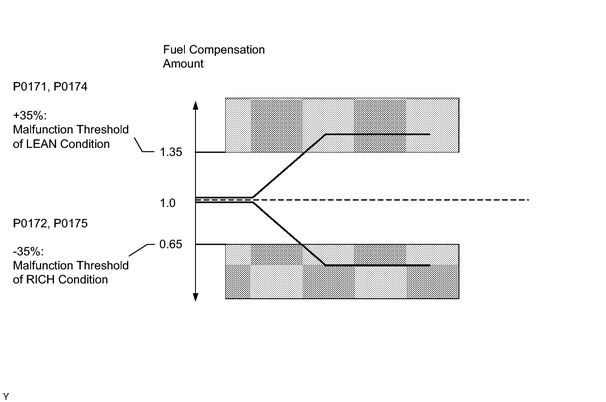
Under closed-loop fuel control, fuel injection amounts that deviate from the ECM's estimated fuel amount will cause a change in the long-term fuel trim compensation value. Long-term fuel trim value is adjusted when persistent deviations in the short-term fuel trim's value are present. Also, the smoothed fuel trim learning value is adjusted when deviations from the ECM's simulated fuel injection value are present. The smoothed fuel trim learning value is the combination of smoothed short-term fuel trim (fuel feedback compensation value) and smoothed long-term fuel trim (learning value of the air fuel ratio). When the smoothed fuel trim learning value exceeds the malfunction threshold, the ECM interprets this as a fault in the fuel system and sets a DTC.
Example:
The average fuel trim learning value is more than +35% or less than -35%, the ECM interprets this as a fuel system malfunction.
MONITOR STRATEGY
|
Related DTCs |
P0171: Fuel trim Lean (bank 1) P0172: Fuel trim Rich (bank 1) P0174: Fuel trim Lean (bank 2) P0175: Fuel trim Rich (bank 2) |
|
Required Sensors/Components (Main) |
Fuel system |
|
Required Sensors/Components (Related) |
Air Fuel Ratio sensor, Engine coolant temperature sensor, Mass Air Flow meter, Crankshaft position sensor |
|
Frequency of Operation |
Continuous |
|
Duration |
Within 10 seconds |
|
MIL Operation |
2 driving cycles |
|
Sequence of Operation |
None |
TYPICAL ENABLING CONDITIONS
|
Monitor will run whenever these DTCs are not present |
P0010, P0020 (OCV Bank 1, 2) P0011 (VVT System 1 - Advance) P0012 (VVT System 1 - Retard) P0021 (VVT System 2 - Advance) P0022 (VVT System 2 - Retard) P0031, P0032, P0051, P0052 (A/F sensor heater - Sensor 1) P0100 - P0103 (MAF meter) P0115 - P0118 (ECT sensor) P0120 - P0223, P2135 (TP sensor) P0125 (Insufficient ECT for closed loop) P0335 (CKP sensor) P0351 - P0358 (Igniter) P0500 (VSS) P2440 (A/R control valve stuck open) P2441 (A/R control valve stuck close) P2444 (AIP stuck ON) P2445 (AIP stuck OFF) |
|
Battery voltage |
11 V or more |
|
Fuel system status |
Closed loop |
|
Either of following conditions (a) or (b) is met |
- |
|
(a) Engine RPM |
Less than 1,000 rpm |
|
(b) Intake air amount per revolution |
0.26 g/rev. or more |
|
Catalyst monitor |
Not executed |
TYPICAL MALFUNCTION THRESHOLDS
|
Purge-cut |
Executing |
|
Either of following conditions (a) or (b) is met |
- |
|
(a) Average between short-term fuel trim and long-term fuel trim |
+35% or more (varies with ECT) |
|
(b) Average between short-term fuel trim and long-term fuel trim |
-35% or less (varies with ECT) |
WIRING DIAGRAM
Refer to DTC P2195
![2007 MY LX470 [08/2006 - ]; 2UZ-FE ENGINE CONTROL SYSTEM: SFI SYSTEM: P2195-P2198; Oxygen (A/F) Sensor Signal Stuck Lean (Bank 1 Sensor 1)+](../../../../stylegraphics/info.gif "2007 MY LX470 [08/2006 - ]; 2UZ-FE ENGINE CONTROL SYSTEM: SFI SYSTEM: P2195-P2198; Oxygen (A/F) Sensor Signal Stuck Lean (Bank 1 Sensor 1)+") .
.
INSPECTION PROCEDURE
HINT:
Intelligent tester only:
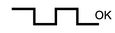
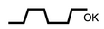
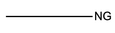
Malfunctioning areas can be identified by performing the A/F CONTROL function provided in the ACTIVE TEST. The A/F CONTROL function can help to determine whether the Air Fuel Ratio (A/F) sensor, Heated Oxygen (HO2) sensor and other potential trouble areas are malfunctioning.
The following instructions describe how to conduct the A/F CONTROL operation using the intelligent tester.
- Connect the intelligent tester to the DLC3.
- Start the engine and turn the tester ON.
- Warm up the engine at an engine speed of 2,500 rpm for approximately 90 seconds.
- On the tester, enter the following menus: DIAGNOSIS / ENHANCED OBD II / ACTIVE TEST / A/F CONTROL.
- Perform the A/F CONTROL operation with the engine in an idling condition (press the RIGHT or LEFT button to change the fuel injection volume).
- Monitor the voltage outputs of the A/F and HO2 sensors (AFS B1S1 and O2S B1S2 or AFS B2S1 and O2S B2S2) displayed on the tester.
HINT:
- The A/F CONTROL operation lowers the fuel injection volume by 12.5% or increases the injection volume by 25%.
- Each sensor reacts in accordance with increases in the fuel injection volume.
Standard:
|
Tester Display (Sensor) |
Injection Volume |
Status |
Voltage |
|---|---|---|---|
|
AFS B1S1 or AFS B2S1 (A/F) |
+25% |
Rich |
Less than 3.0 |
|
AFS B1S1 or AFS B2S1 (A/F) |
-12.5% |
Lean |
More than 3.35 |
|
O2S B1S2 or O2S B2S2 (HO2) |
+25% |
Rich |
More than 0.55 |
|
O2S B1S2 or O2S B2S2 (HO2) |
-12.5% |
Lean |
Less than 0.4 |
NOTICE:
The Air Fuel Ratio (A/F) sensor has an output delay of a few seconds and the Heated Oxygen (HO2) sensor has a maximum output delay of approximately 20 seconds.
|
Case |
A/F Sensor (Sensor 1) Output Voltage |
HO2 Sensor (Sensor 2) Output Voltage |
Main Suspected Trouble Area |
||
|---|---|---|---|---|---|
|
1 |
Injection Volume +25% -12.5% |

|
Injection Volume +25% -12.5% |
|
- |
|
Output Voltage More than 3.35 V Less than 3.0 V |
|
Output Voltage More than 0.55 V Less than 0.4 V |
|
||
|
2 |
Injection Volume +25% -12.5% |
|
Injection Volume +25% -12.5% |
|
|
|
Output Voltage Almost no reaction |
|
Output Voltage More than 0.55 V Less than 0.4 V |
|
||
|
3 |
Injection Volume +25% -12.5% |
|
Injection Volume +25% -12.5% |
|
|
|
Output Voltage More than 3.35 V Less than 3.0 V |
|
Output Voltage Almost no reaction |
|
||
|
4 |
Injection volume +25% -12.5% |
|
Injection Volume +25% -12.5% |
|
|
|
Output Voltage Almost no reaction |
|
Output Voltage Almost no reaction |
|
||
- Following the A/F CONTROL procedure enables technicians to check and graph the voltage outputs of both the A/F and HO2 sensors.
- To display the graph, enter the following menus: DIAGNOSIS / ENHANCED OBD II / ACTIVE TEST / A/F CONTROL / USER DATA / AFS B1S1 and O2S B1S2 or AFS B2S1 and O2S B2S2. Then press the YES button and ENTER button, followed by the F4 button.
HINT:
- Read freeze frame data using the intelligent tester. Freeze frame data records the engine conditions when malfunctions are detected. When troubleshooting, freeze frame data can help determine if the vehicle was running or stopped, if the engine was warmed up or not, if the air fuel ratio was lean or rich, and other data from the time the malfunction occurred.
- A low A/F sensor voltage could be caused by a rich air fuel mixture. Check for conditions that would cause the engine to run rich.
- A high A/F sensor voltage could be caused by a lean air fuel mixture. Check for conditions that would cause the engine to run lean.
PROCEDURE
|
1. |
CHECK OTHER DTC OUTPUT (IN ADDITION TO DTC P0171, P0172, P0174, P0175) |
(a) Connect the intelligent tester to the CAN VIM. Then connect the CAN VIM to the DLC3.
(b) Turn the ignition switch ON and turn the intelligent tester ON.
(c) Enter the following menus: DIAGNOSIS / ENHANCED OBD II / DTC INFO / CURRENT CODES.
(d) Read the DTCs.
|
Display (DTC output) |
Proceed to |
|---|---|
|
P0171, P0172, P0174 or P0175 |
A |
|
P0171, P0172, P0174 or P0175 and other DTCs |
B |
HINT:
If any DTCs other than P0171, P0172, P0173, P0174 and P0175 are output, troubleshoot those DTCs first.
| B |

|
|

|
2. |
CHECK CONNECTION OF VENTILATION HOSE |
OK:
Ventilation hose is connected correctly and is not damaged.
| NG |
|
|
|
3. |
CHECK AIR INDUCTION SYSTEM |
(a) Check the air induction system for vacuum leaks.
OK :
No leakage from air induction system.
| NG |
|
|
|
4. |
PERFORM ACTIVE TEST USING INTELLIGENT TESTER (A/F CONTROL) |
(a) Connect the intelligent tester to the CAN VIM. Then connect the CAN VIM to the DLC3.
(b) Start the engine and turn the tester ON.
(c) Warm up the engine at an engine speed of 2,500 rpm for approximately 90 seconds.
(d) On the tester, enter the following menus: DIAGNOSIS / ENHANCED OBD II / ACTIVE TEST / A/F CONTROL.
(e) Perform the A/F CONTROL operation with the engine in an idling condition (press the RIGHT or LEFT button to change the fuel injection volume.)
(f) Monitor the outputs of A/F and HO2 sensors (AFS B1S1 and O2S B1S2 or AFS B2S1 and O2S B2S2) displayed on the tester.
HINT:
- The A/F CONTROL operation lowers the fuel injection volume by 12.5% or increases the injection volume by 25%.
- Each sensor reacts in accordance with increases in the fuel injection volume.
Standard:
|
Tester Display (Sensor) |
Injection Volume |
Status |
Voltage |
|---|---|---|---|
|
AFS B1S1 or AFS B2S1 (A/F) |
+25% |
Rich |
Less than 3.0 |
|
AFS B1S1 or AFS B2S1 (A/F) |
-12.5% |
Lean |
More than 3.35 |
|
O2S B1S2 or O2S B2S2 (HO2) |
+25% |
Rich |
More than 0.55 |
|
O2S B1S2 or O2S B2S2 (HO2) |
-12.5% |
Lean |
Less than 0.4 |
|
Status AFS B1S1 or AFS B2S1 |
Status O2S B1S2 or O2S B2S2 |
A/F Condition and A/F Sensor Condition |
Misfires |
Suspected Trouble Area |
Proceed to |
|---|---|---|---|---|---|
|
Lean/Rich |
Lean/Rich |
Normal |
- |
- |
C |
|
Lean |
Lean |
Actual air fuel ratio lean |
May occur |
|
A |
|
Rich |
Rich |
Actual air fuel ratio lean |
- |
|
A |
|
Lean |
Lean/Rich |
A/F sensor malfunction |
- |
|
B |
|
Rich |
Lean/Rich |
A/F sensor malfunction |
- |
|
B |
Lean: During A/F CONTROL, the A/F sensor output voltage (AFS) is consistently more than 3.35 V, and the HO2 sensor output voltage (O2S) is consistently less than 0.4 V.
Rich: During A/F CONTROL, the AFS is consistently less than 3.0 V, and the O2S is consistently more than 0.55 V.
Lean/Rich: During A/F CONTROL of the ACTIVE TEST, the output voltage of the heated oxygen sensor alternates correctly.
| B |
|
| C |
|
|
|
5. |
READ VALUE USING INTELLIGENT TESTER (COOLANT TEMP) |
(a) Connect the intelligent tester to the CAN VIM. Then connect the CAN VIM to the DLC3.
(b) Turn the ignition switch ON and turn the tester ON.
(c) Enter the following menus: DIAGNOSIS / ENHANCED OBD II / DATA LIST / PRIMARY.
(d) Read the COOLANT TEMP value when the engine is cold and warmed-up.
Standard:
ECT when the engine is cold: Same as ambient temperature
ECT when the engine is warmed-up: 75 to 95°C (167 to 203°F)
| NG |
|
|
|
6. |
READ VALUE USING INTELLIGENT TESTER (MAF) |
(a) Connect the intelligent tester to the CAN VIM. Then connect the CAN VIM to the DLC3.
(b) Turn the ignition switch ON and turn the tester ON.
(c) Enter the following menus: DIAGNOSIS / ENHANCED OBD II / DATA LIST / PRIMARY / MAF and COOLANT TEMP.
(d) Allow the engine to idle until the COOLANT TEMP reaches 75°C (167°F) or more.
(e) Read the MAF with the engine in an idling condition and at an engine speed of 2, 500 rpm.
Standard:
MAF at idle rpm: 4.0 to 8.0 g/sec. (shift lever is in N position and A/C is OFF)
MAF at 2,500 rpm: 10.0 to 20.0 g/sec. (shift lever is in N position and A/C is OFF)
| NG |
|
|
|
7. |
CHECK FUEL PRESSURE |
Check the fuel pressure
.
| NG |
|
|
|
8. |
CHECK FOR EXHAUST GAS LEAKAGE |
OK:
No gas leakage.
| NG |
|
|
|
9. |
CHECK FOR SPARK AND IGNITION |
HINT:
If the spark plugs or ignition system malfunction, engine misfire may occur. The misfire counter can be read with the intelligent tester. Enter the following menus: DIAGNOSIS / ENHANCED OBD II / DATA LIST / MISFIRE / CYL #1 (to CYL #8).
| NG |
|
|
|
10. |
INSPECT FUEL INJECTOR |
HINT:
If the injectors are malfunctioning, engine misfire may occur. The misfire counter can be read with the intelligent tester. Enter the following menus: DIAGNOSIS / ENHANCED OBD II / DATA LIST / MISFIRE / CYL #1 (to CYL #8).
| NG |
|
|
|
11. |
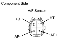
INSPECT AIR FUEL RATIO SENSOR (HEATER RESISTANCE) |
|
(a) Disconnect the A53 and A54 Air Fuel Ratio (A/F) sensor connectors. (b) Measure the resistance of the A/F sensor. Standard resistance:
|
|
| NG |
|
|
|
12. |
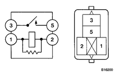
INSPECT A/F RELAY (Marking: A/F HTR) |
|
(a) Remove the A/F relay from the No. 8 engine room relay block. (b) Measure the resistance of the A/F relay. Standard resistance:
|
|
| NG |
|
|
|
13. |
CHECK HARNESS AND CONNECTOR (A/F SENSOR - ECM) |
(a)
Check harness and connector
.
| NG |
|
|
|
14. |
REPLACE AIR FUEL RATIO SENSOR |
(a)
Replace A/F sensor
.
|
|
15. |
PERFORM CONFIRMATION DRIVING PATTERN |
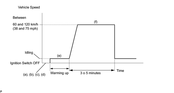
(a) Connect the intelligent tester to the CAN VIM. Then connect the CAN VIM to the DLC3.
(b) Turn the ignition switch ON and turn the tester ON.
(c) Clear DTCs
.
(d) Switch the ECM from normal mode to check mode using the tester
.
(e) Start the engine and warm it up with all the accessories switched OFF.
(f) Drive the vehicle at between 60 and 120 km/h (38 and 75 mph) and at an engine speed of between 1,400 rpm and 3,200 rpm for 3 to 5 minutes.
HINT:
If the system is still malfunctioning, the MIL will be illuminated during step (f).
NOTICE:
If the conditions in this test are not strictly followed, no malfunction will be detected.
|
|
16. |
CHECK WHETHER DTC OUTPUT RECURS (DTC P0171, P0172, P0174 OR P0175) |
(a) On the intelligent tester, enter the following menu: DIAGNOSIS / ENHANCED OBD II / DTC INFO / CURRENT CODES.
(b) Read DTCs.
|
Display (DTC Output) |
Proceed to |
|---|---|
|
No output |
A |
|
P0171, P0172, P0174 or P0175 |
B |
| B |
|
| A |
|

|

|