- Throttle Position (TP) sensor (built into throttle body)
- ECM
| Last Modified: 7-3-2017 | 6.8:8.0.40 | Doc ID: RM000000UII00WX |
| Model Year Start: 2007 | Model: LX470 | Prod Date Range: [08/2006 - ] |
| Title: 2UZ-FE ENGINE CONTROL SYSTEM: SFI SYSTEM: P0120,P0122,P0123,P0220,P0222,P0223,P2135; Throttle / Pedal Position Sensor / Switch "A" Circuit; 2007 MY LX470 [08/2006 - ] | ||
|
DTC |
P0120 |
Throttle / Pedal Position Sensor / Switch "A" Circuit |
|
DTC |
P0122 |
Throttle / Pedal Position Sensor / Switch "A" Circuit Low Input |
|
DTC |
P0123 |
Throttle / Pedal Position Sensor / Switch "A" Circuit High Input |
|
DTC |
P0220 |
Throttle / Pedal Position Sensor / Switch "B" Circuit |
|
DTC |
P0222 |
Throttle / Pedal Position Sensor / Switch "B" Circuit Low Input |
|
DTC |
P0223 |
Throttle / Pedal Position Sensor / Switch "B" Circuit High Input |
|
DTC |
P2135 |
Throttle / Pedal Position Sensor / Switch "A" / "B" Voltage Correlation |
DESCRIPTION
HINT:
- This Electronic Throttle Control System (ETCS) does not use a throttle cable.
- This throttle position sensor is a non-contact type.
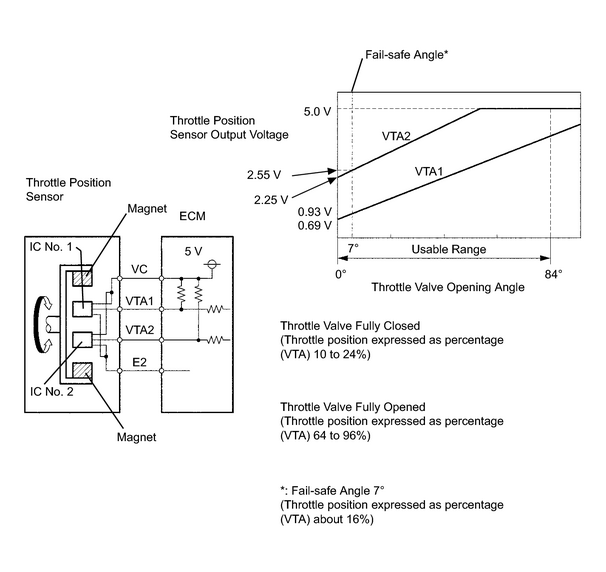
The Throttle Position (TP) sensor is mounted on the throttle body and it detects the opening angle of the throttle valve. This sensor is electronically controlled and uses Hall-effect elements so that accurate control and reliability can be obtained. The throttle position sensor has 2 sensor elements, VTA1 and VTA2, each with their own signal outputs. VTA1 is used to detect the throttle opening angle and VTA2 is used to detect malfunctions in VTA1. Voltage applied to VTA1 and VTA2 changes between 0 V to 5 V in proportion to the opening angle of the throttle valve. There are several checks that the ECM performs to confirm proper operation of the throttle position sensor.
The ECM judges the current opening angle of the throttle valve from these signals input from terminals VTA1 and VTA2, and the ECM controls the throttle actuator to set the throttle valve angle properly in response to driver inputs.
|
DTC No. |
DTC Detection Condition |
Trouble Area |
|---|---|---|
|
P0120 |
VTA1 is 0.2 V or less or VTA1 is 4.535 V or more (for 2 seconds) (1 trip detection logic) |
|
|
P0122 |
VTA1 is 0.2 V or less (for 2 seconds) (1 trip detection logic) |
|
|
P0123 |
VTA1 is 4.535 V or more (for 2 seconds) (1 trip detection logic) |
|
|
P0220 |
VTA2 is 1.75 V or less, or VTA2 is 4.8 V or more VTA1 is 0.2 V or more, and VTA1 is 2.02 V or less (1 trip detection logic) |
|
|
P0222 |
VTA2 is 1.75 V or less (for 2 seconds) (1 trip detection logic) |
|
|
P0223 |
VTA2 is 4.8 V or more when VTA1 is between 0.2 to 2.02 V (for 2 seconds) (1 trip detection logic) |
|
|
P2135 |
|
|
HINT:
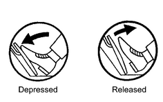
- After confirming DTCs, use the intelligent tester to confirm the throttle valve opening percentage and throttle position sensor condition. Enter the following menus: DIAGNOSIS / ENHANCED OBD II / DATA LIST / ETCS / THROTTLE POS AND THROTTLE POS #2.
- THROTTLE POS is the VTA1 signal. THROTTLE POS #2 is the VTA2 signal.
Reference (Normal condition):
|
Tester Display |
Accelerator Pedal Fully Released |
Accelerator Pedal Fully Depressed |
|---|---|---|
|
THROTTLE POS |
10 to 24% |
64 to 96% |
|
THROTTLE POS #2 |
2.1 to 3.1 V |
4.5 to 5.0 V |
MONITOR DESCRIPTION
-
The ECM uses the throttle position sensor to monitor the throttle valve opening angle.
-
There is a specific voltage difference expected between VTA1 and VTA2 for each throttle opening angle.
If the difference between VTA1 and VTA2 is incorrect, the ECM interprets this as a fault and will set a DTC.
-
VTA1 and VTA2 each have a specific voltage operating range.
If VTA1 or VTA2 is out of the normal operating range, the ECM interprets this as a fault and will set a DTC.
-
VTA1 and VTA2 should never be close to the same voltage levels.
If VTA1 is within 0.02 V of VTA2, the ECM interprets this as a short circuit in the throttle position sensor system and will set a DTC.
This monitor runs for 2 seconds (the first 2 seconds of engine idle) after the engine is started (1 trip detection logic).
-
There is a specific voltage difference expected between VTA1 and VTA2 for each throttle opening angle.
MONITOR STRATEGY
|
Related DTCs |
P0120: Throttle position sensor 1 range check (fluctuating) P0122: Throttle position sensor 1 range check (low voltage) P0123: Throttle position sensor 1 range check (high voltage) P0220: Throttle position sensor 2 range check (fluctuating) P0222: Throttle position sensor 2 range check (low voltage) P0223: Throttle position sensor 2 range check (high voltage) P2135: Throttle position sensor range check (correlation) |
|
Required sensors/components (Main) |
Throttle position sensor |
|
Required sensors/components (Related) |
- |
|
Frequency of operation |
Continuous |
|
Duration |
Throttle position sensor 1 range check (flutterting): 2 seconds (accelerator pedal ON) Throttle position sensor 1 range check (low voltage): 2 seconds (accelerator pedal ON) Throttle position sensor 1 range check (high voltage): 2 seconds (accelerator pedal ON) Throttle position sensor 2 range check (fluctuating): 2 seconds (accelerator pedal ON) Throttle position sensor 2 range check (low voltage): 2 seconds (accelerator pedal ON) Throttle position sensor 2 range check (high voltage): 2 seconds (accelerator pedal ON) Throttle position sensor 1 range check (fluctuating): 10 seconds (accelerator pedal OFF Throttle position sensor 1 range check (low voltage): 10 seconds (accelerator pedal OFF) Throttle position sensor 1 range check (high voltage): 10 seconds (accelerator pedal OFF) Throttle position sensor 2 range check (fluctuating): 10 seconds (accelerator pedal OFF) Throttle position sensor 2 range check (low voltage): 10 seconds (accelerator pedal OFF) Throttle position sensor 2 range check (high voltage): 10 seconds (accelerator pedal OFF) Throttle position sensor range check (correlation): Within 0.5 seconds or 0.4 seconds |
|
MIL operation |
Immediate |
|
Sequence of operation |
None |
TYPICAL ENABLING CONDITIONS
|
Monitor will run whenever these DTCs are not present |
None |
TYPICAL MALFUNCTION THRESHOLDS
P0120:
|
VTA1 voltage |
0.2 V or less or 4.535 V or more |
P0122:
|
VTA1 voltage |
0.2 V or less |
P0123:
|
VTA1 voltage |
4.535 V or more |
P0220:
|
VTA2 voltage |
1.75 V or less or 4.8 V or more |
P0222:
|
VTA2 voltage |
1.75 V or less |
P0223:
|
VTA2 voltage when the VTA1 is 0.2 to 2.02 V |
4.8 V or more |
P2135:
|
Either of the following condition A or B is met |
- |
|
Condition A |
- |
|
Difference between VTA and VTA2 voltage |
0.02 V or less |
|
Condition B |
- |
|
VTA1 voltage |
0.2 V or less |
|
VTA2 voltage |
1.75 V or less |
COMPONENT OPERATING RANGE
|
VTA1 voltage |
0.69 to 4.05 V |
|
VTA2 voltage |
2.25 to 4.8 V |
FAIL-SAFE
When any of these DTCs, as well as other DTCs relating to Electronic Throttle Control System (ETCS) malfunctions, are set, the ECM enters fail-safe mode. During fail-safe mode, the ECM cuts the current to the throttle actuator off, and the throttle valve is returned to a 7°throttle angle by the return spring. The ECM then adjusts the engine output by controlling the fuel injection (intermittent fuel-cut) and ignition timing, in accordance with the accelerator pedal opening angle, to allow the vehicle to continue at a minimal speed.
If the accelerator pedal is depressed firmly and gently, the vehicle can be driven slowly.
Fail-safe mode continues until a pass condition is detected, and the ignition switch is then turned OFF.
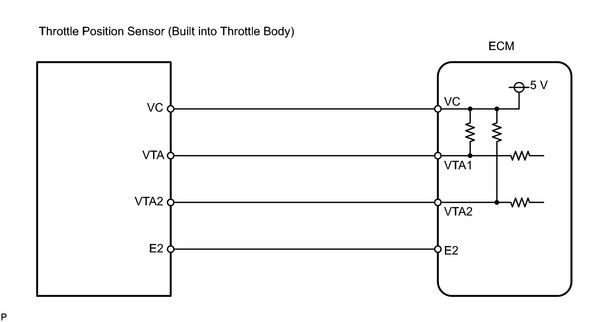
WIRING DIAGRAM
INSPECTION PROCEDURE
HINT:
- If DTCs related to different systems that have terminal E2 as the ground terminal are output simultaneously, terminal E2 may have an open circuit.
- Read freeze frame data using the intelligent tester. Freeze frame data records the engine conditions when malfunctions are detected. When troubleshooting, freeze frame data can help determine if the vehicle was running or stopped, if the engine was warmed up or not, if the air fuel ratio was lean or rich, and other data from the time the malfunction occurred.
- This is the repair procedure of the throttle position sensor.
PROCEDURE
|
1. |
READ VALUE USING INTELLIGENT TESTER (THROTTLE POS, THROTTLE POS #2) |
|
(a) Connect the intelligent tester to the CAN VIM. Then connect the CAN VIM to the DLC3. (b) Turn the ignition switch ON and turn the intelligent tester ON. (c) Enter the following menus: DIAGNOSIS / ENHANCED OBD II / DATA LIST / ETCS / THROTTLE POS and THROTTLE POS #2 . (d) Read the value.
|
|
||||||||||||||||||||||||||||||||||||||||||||
| B |

|
|

|
2. |
CHECK HARNESS AND CONNECTOR (THROTTLE POSITION SENSOR - ECM) |
(a)
Check harness and connector
![2007 MY LX470 [08/2006 - ]; INTRODUCTION: HOW TO TROUBLESHOOT ECU CONTROLLED SYSTEMS: ELECTRONIC CIRCUIT INSPECTION PROCEDURE](../../../../stylegraphics/info.gif "2007 MY LX470 [08/2006 - ]; INTRODUCTION: HOW TO TROUBLESHOOT ECU CONTROLLED SYSTEMS: ELECTRONIC CIRCUIT INSPECTION PROCEDURE") .
.
| NG |
|
|
|
3. |
CHECK ECM (VC VOLTAGE) |
|
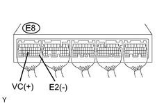
(a) Disconnect the T24 throttle body connector. (b) Turn the ignition switch ON. (c) Measure the voltage of the ECM. Standard voltage:
|
|
| NG |
|
|
|
4. |
REPLACE THROTTLE BODY |
(a)
Replace throttle body
.
|
|
5. |
READ OUTPUT DTC (THROTTLE POSITION SENSOR DTCS ARE OUTPUT AGAIN) |
(a) Connect the intelligent tester to the CAN VIM. Then connect the CAN VIM to the DLC3.
(b) Turn the ignition switch ON and turn the intelligent tester ON.
(c)
Clear the DTC
.
(d) Start the engine and allow the engine to idle for 15 seconds or more.
(e) Enter the following menus: DIAGNOSIS / ENHANCED OBD II / DTC INFO / CURRENT CODES.
(f) Read the DTC.
|
Display (DTC output) |
Proceed to |
|---|---|
|
P0120, P0122, P0123, P0220, P0222, P0223 or P2135 |
A |
|
No output |
B |
| B |
|
| A |
|

|

|