| Last Modified: 7-3-2017 | 6.8:8.0.40 | Doc ID: RM000000V2500CX |
| Model Year Start: 2007 | Model: LX470 | Prod Date Range: [08/2006 - ] |
| Title: 2UZ-FE COOLING: WATER PUMP: INSTALLATION; 2007 MY LX470 [08/2006 - ] | ||
INSTALLATION
1. INSTALL WATER PUMP ASSEMBLY
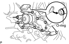
(a) Install a new O-ring to the water by-pass pipe end.
(b) Apply soapy water to the O-ring.
(c) Connect the water pump to the water by-pass pipe end.
|
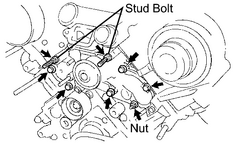
(d) Install the water pump and a new gasket with the 5 bolts, 2 stud bolts and nut. Uniformly tighten the bolts, stud bolts and nut in several passes. Torque: 21 N·m {214 kgf·cm, 15ft·lbf} for bolt 18 N·m {194 kgf·cm, 24ft·lbf} for nut and stud bolt HINT: Use bolts 35 mm (1.38 in.) in length. |
|
2. INSTALL WATER INLET HOUSING
(a) Remove any old packing (FIPG) material and be careful not to drop any oil on the contact surfaces of the water inlet housing and water pump.
HINT:
- Using a razor blade and gasket scraper, remove all the old packing (FIPG) material from the gasket surfaces and sealing groove.
- Thoroughly clean all components to remove all the loose material.
- Using a non-residue solvent, clean both sealing surfaces.
|
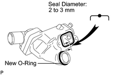
(b) Apply seal packing to the sealing groove of the water inlet housing as shown in the illustration. Seal packing: Part No. 08826-00100 or equivalent Seal diameter: 2 to 3 mm (0.078 to 0.118 in.) HINT:
|
|
(c) Install a new O-ring to the water inlet housing.
(d) Apply soapy water on the O-ring.
(e) Attach the water inlet housing end to the front water by-pass joint tube.
|
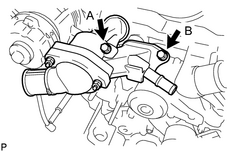
(f) Install the water inlet and housing assembly with the 2 bolts. Alternately tighten the 2 bolts. Torque: 18 N·m {184 kgf·cm, 13ft·lbf} HINT: Each bolt length is indicated below. Standard bolt length:
|
|
3. INSTALL NO. 2 TIMING BELT IDLER PULLEY SUB-ASSEMBLY
(a) Install the idler pulley with the bolt.
Torque:
34.5 N·m {352 kgf·cm, 25ft·lbf}
4. INSTALL TIMING BELT
(a)
Install the timing belt
![2007 MY LX470 [08/2006 - ]; 2UZ-FE ENGINE MECHANICAL: TIMING BELT: INSTALLATION+](../../../../stylegraphics/info.gif "2007 MY LX470 [08/2006 - ]; 2UZ-FE ENGINE MECHANICAL: TIMING BELT: INSTALLATION+") .
.
5.
INSTALL OIL COOLER PIPE
6. INSTALL RADIATOR ASSEMBLY
(a)
Install the radiator assembly
.
7.
INSTALL DRIVE BELT
8.
INSTALL COOLER COMPRESSOR ASSEMBLY
9.
INSTALL INTAKE AIR CONNECTOR PIPE
10.
INSTALL V-BANK COVER SUB-ASSEMBLY
11.
ADD ENGINE COOLANT
12.
INSTALL NO. 1 ENGINE UNDER COVER
13. CONNECT CABLE TO NEGATIVE BATTERY TERMINAL
14. PERFORM INITIALIZATION
(a)
Perform initialization
.
NOTICE:
Certain systems need to be initialized after disconnecting and reconnecting the cable from the negative (-) battery terminal.
15. CHECK FOR ENGINE COOLANT LEAKS
(a)
Check for engine coolant leaks
.

|

|