- Short in stop light switch signal circuit
- Stop light switch
- ECM
| Last Modified: 7-3-2017 | 6.8:8.0.40 | Doc ID: RM000000W8802OX |
| Model Year Start: 2007 | Model: LX470 | Prod Date Range: [08/2006 - ] |
| Title: A750F AUTOMATIC TRANSMISSION: AUTOMATIC TRANSMISSION SYSTEM: P0724; Brake Switch "B" Circuit High; 2007 MY LX470 [08/2006 - ] | ||
|
DTC |
P0724 |
Brake Switch "B" Circuit High |
DESCRIPTION
The purpose of this circuit is to prevent the engine from stalling while driving in the lock-up condition when the brakes are suddenly applied.
When the brake pedal is depressed, this switch sends a signal to the ECM. Then the ECM cancels the operation of the lock-up clutch while braking is in progress.
|
DTC No. |
DTC Detection Condition |
Trouble Area |
|---|---|---|
|
P0724 |
Stop light switch remains ON even when vehicle is driven in GO (30 km/h (18.63 mph) or more) and STOP (less than 3 km/h (1.86 mph)) pattern 5 times (2 trip detection logic) |
|
MONITOR DESCRIPTION
This DTC indicates that the stop light switch remains ON. When the stop light switch remains ON during GO and STOP driving, the ECM interprets this as a fault in the stop light switch. Then the MIL illuminates and the ECM stores the DTC. The vehicle must GO (30 km/h (18.63 mph) or more) and STOP (less than 3 km/h (1.86 mph)) 5 times for 2 driving cycles in order for the DTC to be output.
MONITOR STRATEGY
|
Related DTCs |
P0724: Stop light switch/Range check/Rationality |
|
Required sensors/Components |
Stop light switch, Vehicle speed sensor |
|
Frequency of operation |
Continuous |
|
Duration |
GO and STOP 5 times |
|
MIL operation |
2 driving cycles |
|
Sequence of operation |
None |
TYPICAL ENABLING CONDITIONS
The stop light switch remains on during GO and STOP 5 times.
GO and STOP is defined as follows:|
The monitor will run whenever this DTC is not present. |
None |
|
GO: (Vehicle speed is 30 km/h (18.63 mph) or more) |
Once |
|
STOP: (Vehicle speed is less than 3 km/h (1.86 mph)) |
Once |
|
Starter |
OFF |
|
Battery voltage |
8 V or more |
|
Ignition switch |
ON |
TYPICAL MALFUNCTION THRESHOLDS
|
Brake switch |
Stuck ON |
WIRING DIAGRAM
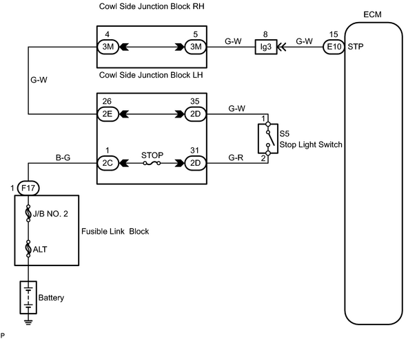
INSPECTION PROCEDURE
PROCEDURE
|
1. |
READ VALUE USING DATA LIST (STP SIGNAL) |
HINT:
Using the intelligent tester's DATA LIST allows switch, sensor, actuator and other item values to be read without removing any parts. Reading the DATA LIST early in troubleshooting is one way to save time.
NOTICE:
In the table below, the values listed under "Normal Condition" are reference values. Do not depend solely on these reference values when deciding whether a part is faulty or not.
- Warm up the engine.
- Turn the ignition switch OFF.
- Connect the intelligent tester to the CAN VIM. Then connect the CAN VIM to the DLC3.
- Turn the ignition switch ON.
- Turn the intelligent tester ON.
- Enter the following menus: DIAGNOSIS / OBD/MOBD / ECT / DATA LIST.
- Read the DATA LIST using the intelligent tester.
|
Tester Display |
Measurement Item/Range |
Normal Condition |
Diagnostic Note |
|---|---|---|---|
|
STOP LIGHT SW |
Stop light switch status/ ON or OFF |
Brake pedal is
|
- |
| OK |

|
|

|
2. |
INSPECT STOP LIGHT SWITCH |
|
(a) Remove the stop light switch. |
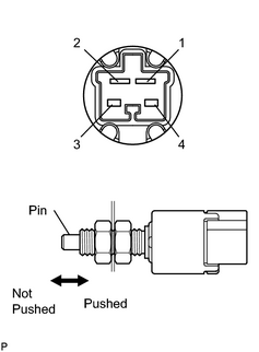
|
(b) Measure the resistance of the switch.
Standard resistance:
|
Tester Connection |
Switch Condition |
Specified Condition |
|---|---|---|
|
1 - 2 |
Pin pushed (pedal released) |
10 kΩ or higher |
|
1 - 2 |
Pin not pushed (pedal depressed) |
Below 1 Ω |
|
3 - 4 |
Pin pushed (pedal released) |
10 kΩ or higher |
|
3 - 4 |
Pin not pushed (pedal depressed) |
Below 1 Ω |
| NG |
|
|
|
3. |
CHECK WIRE HARNESS (ECM - BATTERY) |
(a)
Check wire harness
![2007 MY LX470 [08/2006 - ]; INTRODUCTION: HOW TO TROUBLESHOOT ECU CONTROLLED SYSTEMS: ELECTRONIC CIRCUIT INSPECTION PROCEDURE](../../../../stylegraphics/info.gif "2007 MY LX470 [08/2006 - ]; INTRODUCTION: HOW TO TROUBLESHOOT ECU CONTROLLED SYSTEMS: ELECTRONIC CIRCUIT INSPECTION PROCEDURE") .
.
| NG |
|
| OK |
|

|

|