- Open or short in shift solenoid valve SLT circuit
- Shift solenoid valve SLT
- ECM
| Last Modified: 7-3-2017 | 6.8:8.0.40 | Doc ID: RM000000W8A02CX |
| Model Year Start: 2007 | Model: LX470 | Prod Date Range: [08/2006 - ] |
| Title: A750F AUTOMATIC TRANSMISSION: AUTOMATIC TRANSMISSION SYSTEM: P2716; Pressure Control Solenoid "D" Electrical (Shift Solenoid Valve SLT); 2007 MY LX470 [08/2006 - ] | ||
|
DTC |
P2716 |
Pressure Control Solenoid "D" Electrical (Shift Solenoid Valve SLT) |
DESCRIPTION
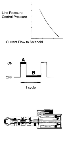
The linear solenoid valve (SLT) controls the transmission line pressure for smooth transmission operation based on signals from the throttle position sensor and the vehicle speed sensor. The ECM adjusts the duty ratio* of the SLT solenoid valve to control hydraulic line pressure coming from the primary regulator valve. Appropriate line pressure assures smooth shifting with varying engine outputs.
HINT:
*: The duty ratio is the ratio of the current ON time (A) to the total of the current ON and OFF time (A + B).
Duty Ratio (%) = A / (A + B) x 100
|
DTC No. |
DTC Detection Condition |
Trouble Area |
|---|---|---|
|
P2716 |
Open or short is detected in shift solenoid valve SLT circuit for 1 second or more while driving (1 trip detection logic) |
|
|
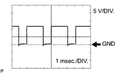
1. Reference: Inspect using an oscilloscope. Check the waveform of the ECM connector. Standard voltage: Refer to illustration.
|
|
MONITOR DESCRIPTION
When an open or short in the linear solenoid valve SLT circuit is detected, the ECM interprets this as a fault. The ECM will illuminate the MIL and store the DTC.
MONITOR STRATEGY
|
Related DTCs |
P2716: Shift solenoid valve SLT/Range check |
|
Required sensors/Components |
Shift solenoid valve SLT |
|
Frequency of operation |
Continuous |
|
Duration |
1 sec. |
|
MIL operation |
Immediate |
|
Sequence of operation |
None |
TYPICAL ENABLING CONDITIONS
All
|
The monitor will run whenever this DTC is not present. |
None |
Case 1
|
Solenoid current cut status |
Not cut |
|
Battery voltage |
11 V or more |
|
Ignition switch |
ON |
|
Starter |
OFF |
Case 2
|
Battery voltage |
8 V or more |
|
Ignition switch |
ON |
|
Starter |
OFF |
TYPICAL MALFUNCTION THRESHOLDS
Case 1
|
Solenoid status (SLT) from IC |
Fail (Open or short) |
Case 2
|
Hybrid IC status |
Fail |
COMPONENT OPERATING RANGE
|
Output signal duty |
Less than 100% |
WIRING DIAGRAM
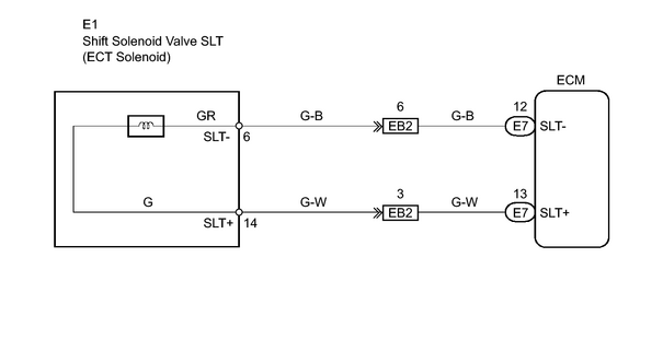
INSPECTION PROCEDURE
PROCEDURE
|
1. |
INSPECT TRANSMISSION WIRE (SHIFT SOLENOID VALVE SLT) |
|
(a) Disconnect the E1 wire connector. |
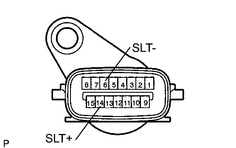
|
(b) Measure the resistance of the transmission wire.
Standard resistance:
|
Tester Connection |
Condition |
Specified Condition |
|---|---|---|
|
14 (SLT+) - 6 (SLT-) |
20°C (68°F) |
5.0 to 5.6 Ω |
|
14 (SLT+) - Body ground |
20°C (68°F) |
10 kΩ or higher |
|
6 (SLT-) - Body ground |
20°C (68°F) |
10 kΩ or higher |
| NG |

|
|

|
2. |
CHECK WIRE HARNESS (TRANSMISSION WIRE - ECM) |
|
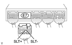
(a) Disconnect the E7 ECM connector. |
|
(b) Measure the resistance of the wire harness side connector.
Standard resistance:
|
Tester Connection |
Condition |
Specified Condition |
|---|---|---|
|
E7-13 (SLT+) - E7-12 (SLT-) |
20°C (68°F) |
5.0 to 5.6 Ω |
|
E7-13 (SLT+) - Body ground |
20°C (68°F) |
10 kΩ or higher |
|
E7-12 (SLT-) - Body ground |
20°C (68°F) |
10 kΩ or higher |
| NG |
|
| OK |
|
|
3. |
INSPECT SHIFT SOLENOID VALVE SLT |
|
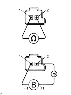
(a) Remove the shift solenoid valve SLT. (b) Measure the resistance of the solenoid valve. Standard resistance: 5.0 to 5.6 Ωat 20°C (68°F) (c) Connect the battery's positive (+) lead to the terminal of the solenoid connector, and the negative (-) lead to the solenoid body. OK: Solenoid makes operating noise. |
|
| NG |
|
| OK |
|

|

|