- "ENGINE" is not displayed on "Communication BUS CHECK" of intelligent tester
| Last Modified: 7-3-2017 | 6.8:8.0.40 | Doc ID: RM000000WIP019X |
| Model Year Start: 2007 | Model: LX470 | Prod Date Range: [08/2006 - ] |
| Title: CAN COMMUNICATION: CAN COMMUNICATION SYSTEM: ECM Communication Stop Mode; 2007 MY LX470 [08/2006 - ] | ||
|
ECM Communication Stop Mode |
DESCRIPTION
|
Detection Item |
Symptom |
Trouble Area |
|---|---|---|
|
ECM communication stop mode |
|
Power source or inside ECM |
WIRING DIAGRAM
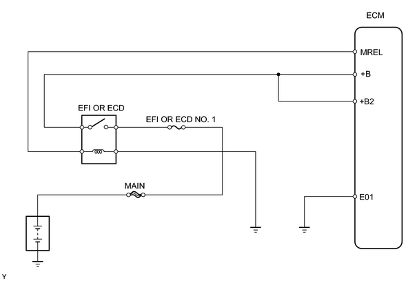
INSPECTION PROCEDURE
PROCEDURE
|
1. |
INSPECT RELAY (Marking: EFI OR ECD) |
|
(a) Remove the EFI OR ECD relay from engine room relay block. |
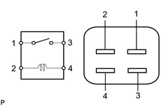
|
(b) Measure the resistance of the relay.
Standard resistance:
|
Tester Condition |
Specified Condition |
|---|---|
|
1 - 3 |
10 kΩ or higher |
|
1 - 3 |
Below 1 Ω (when battery voltage is applied to terminals 2 and 4) |
| NG |

|
|

|
2. |
CHECK WIRE HARNESS (ENGINE ROOM JUNCTION BLOCK - ECM, BATTERY AND BODY GROUND) |
|
(a) Remove the EFI OR ECD relay from the engine room relay block. |
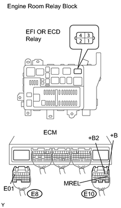
|
(b) Disconnect the E8 and E10 ECM connectors.
(c) Measure the voltage of the wire harness side connector.
Standard voltage:
|
Tester Connection |
Specified Condition |
|---|---|
|
R/B EFI OR ECD relay terminal 3- Body ground |
10 to 14 V |
(d) Measure the resistance of the wire harness side connectors.
Standard resistance:
|
Tester Connection |
Specified Condition |
|---|---|
|
R/B EFI OR ECD relay terminal 4 - E10-8 (MREL) |
Below 1 Ω |
|
R/B EFI OR ECD relay terminal 2- Body ground |
Below 1 Ω |
|
R/B EFI OR ECD relay terminal 1- E10-1 (+B) |
Below 1 Ω |
|
R/B EFI OR ECD relay terminal 1- E10-2 (+B2) |
Below 1 Ω |
|
E8-7 (E01) - Body ground |
Below 1 Ω |
| NG |
|
| OK |
|

|

|