- Vehicle speed sensor
- Tire pressure warning ECU and receiver
- Combination meter
- Wire harness or connector
| Last Modified: 7-3-2017 | 6.8:8.0.40 | Doc ID: RM000000XNA00YX |
| Model Year Start: 2007 | Model: LX470 | Prod Date Range: [08/2006 - ] |
| Title: TIRE AND WHEEL: TIRE PRESSURE WARNING SYSTEM: C2191/91; Vehicle Speed Signal Error (Test Mode DTC); 2007 MY LX470 [08/2006 - ] | ||
|
DTC |
C2191/91 |
Vehicle Speed Signal Error (Test Mode DTC) |
DESCRIPTION
The tire pressure warning ECU and receiver receives a speed signal from the combination meter. This DTC is stored upon entering test mode, and cleared when a vehicle speed signal of 12 mph (20 km/h) is detected for 3 seconds or more. This DTC is output only in test mode.
|
DTC Code |
Detection Condition |
Trouble Area |
|---|---|---|
|
C2191/91 |
Speed sensor circuit malfunction |
|
WIRING DIAGRAM
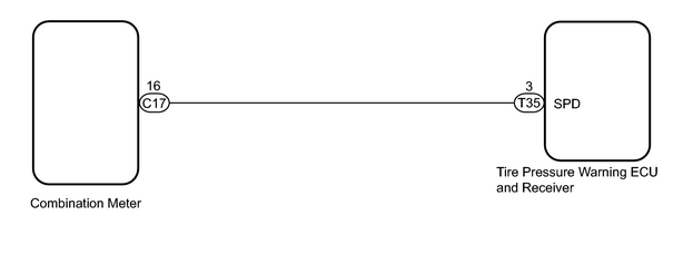
INSPECTION PROCEDURE
NOTICE:
- When replacing the tire pressure warning ECU and receiver, read the IDs stored in the old ECU using the intelligent tester and write them down before removal.
-
It is necessary to perform initialization
![2007 MY LX470 [08/2006 - ]; TIRE AND WHEEL: TIRE PRESSURE WARNING SYSTEM: INITIALIZATION](../../../../stylegraphics/info.gif "2007 MY LX470 [08/2006 - ]; TIRE AND WHEEL: TIRE PRESSURE WARNING SYSTEM: INITIALIZATION") after registration
of the transmitter IDs into the tire pressure warning ECU and receiver after the ECU and/or valve and transmitter has been replaced.
after registration
of the transmitter IDs into the tire pressure warning ECU and receiver after the ECU and/or valve and transmitter has been replaced.
PROCEDURE
|
1. |
READ VALUE USING DATA LIST (VEHICLE SPEED) |
(a) Turn the ignition switch OFF.
(b) Connect the intelligent tester to the DLC3.
(c) Turn the ignition switch ON and the tester on.
(d) Following the display on the intelligent tester, select the "DATA LIST".
(e) Check the values by referring to the table below.
(f) Check that the values indicated on the tester and on the combination meter are the same.
Tire pressure warning ECU and receiver
|
Tester Display |
Measurement Item/Range |
Normal Condition |
Diagnostic Note |
|---|---|---|---|
|
VEHICLE SPEED |
Vehicle speed/ min.: 0 km/h (0 mph) max.: 255 km/h (158 mph) |
Almost same as actual vehicle speed |
- |
OK:
Vehicle speed indicated on the intelligent tester indicates the actual speed.
| OK |

|
|

|
2. |
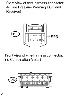
CHECK HARNESS AND CONNECTOR (ECU - COMBINATION METER) |
(a) Disconnect the T35 ECU connector.
|
(b) Disconnect the C17 meter connector. |
|
(c) Measure the resistance according to the value(s) in the table below.
Standard resistance:
|
Tester Connection |
Condition |
Specified Condition |
|---|---|---|
|
T35-3 (SPD) - C17-16 |
Always |
Below 1 Ω |
|
T35-3 (SPD) - Body ground |
Always |
10 kΩ or higher |
| NG |
|
| OK |
|

|

|