| Last Modified: 7-3-2017 | 6.8:8.0.40 | Doc ID: RM000000XVK01BX |
| Model Year Start: 2007 | Model: LX470 | Prod Date Range: [08/2006 - ] |
| Title: CAN COMMUNICATION: CAN COMMUNICATION SYSTEM: TERMINALS OF ECU; 2007 MY LX470 [08/2006 - ] | ||
TERMINALS OF ECU
NOTICE:
This section describes the standard CAN values for all CAN related components.
1. JUNCTION CONNECTOR
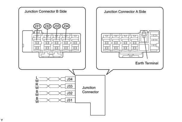
Wiring color
|
Junction Connector B side |
Color (CAN-H Side) |
Color (CAN-L Side) |
|---|---|---|
|
ECM (J31) |
B |
W |
|
Gateway ECU (J32) |
B |
W |
|
Translate ECU (J33) |
R |
W |
|
DLC3 (J34) |
L |
W |
HINT:
- The connectors connected to the junction connector can be distinguished by the colors of the bus lines and the connecting side of the connector.
- The connectors can be connected to any terminals on the same side.
|
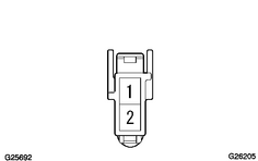
2. TERMINALS OF CONNECTORS FOR JUNCTION CONNECTOR
|
|
3. CHECK DLC3
|
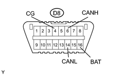
(a) Measure the resistance of the connector.
|
|
4. CHECK ECM
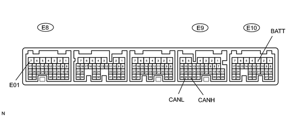
(a) Measure the resistance of the connector.
|
Symbols (Terminal No.) |
Wiring Color |
Condition |
Specified Condition |
|---|---|---|---|
|
CANH (E9-33) - CANL (E9-34) |
B - W |
Ignition switch OFF |
54 to 67 Ω |
(b) Disconnect the E8, E9 and E10 ECM connectors.
(c) Measure the resistance of the wire harness side connectors.
|
Symbols (Terminal No.) |
Wiring Color |
Condition |
Specified Condition |
|---|---|---|---|
|
CANH (E9-33) - CANL (E9-34) |
B - W |
Ignition switch OFF |
108 to 132 Ω |
|
CANH (E9-33) - E01 (E8-7) |
B - W-B |
Ignition switch OFF |
3 kΩ or higher |
|
CANL (E9-34) - E01 (E8-7) |
W - W-B |
Ignition switch OFF |
3 kΩ or higher |
|
CANH (E9-33) - BATT (E10-3) |
B - B-R |
Ignition switch OFF |
1 MΩ or higher |
|
CANL (E9-34) - BATT (E10-3) |
W - B-R |
Ignition switch OFF |
1 MΩ or higher |
5. CHECK GATEWAY ECU
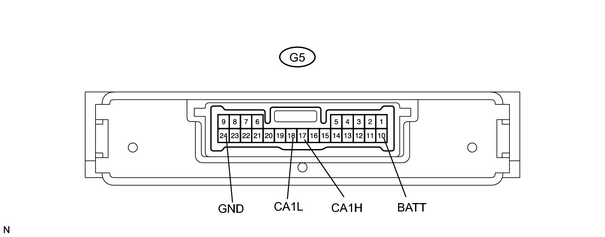
(a) Measure the resistance of the connector.
|
Symbols (Terminal No.) |
Wiring Color |
Condition |
Specified Condition |
|---|---|---|---|
|
CA1H (G5-17) - CA1L (G5-18) |
B - W |
Ignition switch OFF |
54 to 67 Ω |
(b) Disconnect the G5 ECU connector.
(c) Measure the resistance of the wire harness side connector.
|
Symbols (Terminal No.) |
Wiring Color |
Condition |
Specified Condition |
|---|---|---|---|
|
CA1H (G5-17) - CA1L (G5-18) |
B - W |
Ignition switch OFF |
108 to 132 Ω |
|
CA1H (G5-17) - GND (G5-24) |
B - W-B |
Ignition switch OFF |
3 kΩ or higher |
|
CA1L (G5-18) - GND (G5-24) |
W - W-B |
Ignition switch OFF |
3 kΩ or higher |
|
CA1H (G5-17) - BATT (G5-10) |
B - L-W |
Ignition switch OFF |
1 MΩ or higher |
|
CA1L (G5-18) - BATT (G5-10) |
W - L-W |
Ignition switch OFF |
1 MΩ or higher |
6. CHECK TRANSLATE ECU
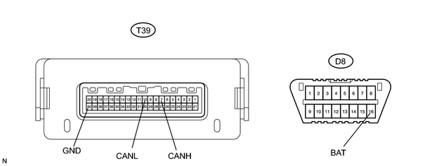
(a) Disconnect the T39 ECU connector.
(b) Measure the resistance of the wire harness side connectors.
|
Symbols (Terminal No.) |
Wiring Color |
Condition |
Specified Condition |
|---|---|---|---|
|
CANH (T39-7) - CANL (T39-10) |
R - W |
Ignition switch OFF |
54 to 67 Ω |
|
CANH (T39-7) - GND (T39-40) |
R - W-B |
Ignition switch OFF |
3 kΩ or higher |
|
CANL (T39-10) - GND (T39-40) |
W - W-B |
Ignition switch OFF |
3 kΩ or higher |
|
CANH (T39-7) - BAT (D8-16) |
R - B-W |
Ignition switch OFF |
1 MΩ or higher |
|
CANL (T39-10) - BAT (D8-16) |
W - B-W |
Ignition switch OFF |
1 MΩ or higher |

|

|