| Last Modified: 7-3-2017 | 6.8:8.0.40 | Doc ID: RM000000XZD00QX |
| Model Year Start: 2007 | Model: LX470 | Prod Date Range: [08/2006 - ] |
| Title: STEERING COLUMN: POWER TILT AND POWER TELESCOPIC STEERING COLUMN SYSTEM: Actuator Power Source Circuit; 2007 MY LX470 [08/2006 - ] | ||
|
Actuator Power Source Circuit |
DESCRIPTION
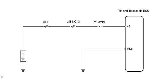
This is the power source for the motors.
WIRING DIAGRAM
INSPECTION PROCEDURE
PROCEDURE
|
1. |
CHECK TILT AND TELESCOPIC ECU (+B VOLTAGE) |
|
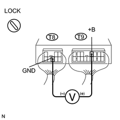
(a) Remove the ECU with the connectors still connected. |
|
(b) Measure the voltage between terminals +B and GND of the T8 and T9 ECU connectors.
Standard voltage:
8 to 16 V
| OK |

|
PROCEED TO NEXT CIRCUIT INSPECTION SHOWN ON PROBLEM SYMPTOMS TABLE |
|

|
2. |
CHECK TILT AND TELESCOPIC ECU (GROUND) |
|
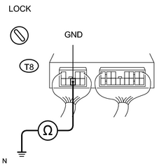
(a) Measure the resistance between terminal GND of the T8 ECU connector and body ground. Standard resistance: Below 1 Ω |
|
| NG |
|
|
|
3. |
INSPECT FUSE (TIL&TEL) |
(a) Remove the TIL&TEL fuse from the cowl side junction block RH.
(b) Measure the resistance of the fuse.
Standard resistance:
Below 1Ω
| NG |
|
| OK |
|
PROCEED TO NEXT CIRCUIT INSPECTION SHOWN ON PROBLEM SYMPTOMS TABLE |

|

|