-
Transfer L4 position switch remains ON while vehicle is running under following conditions for 1.8 seconds or more (1 trip detection logic):
- Output shaft speed 1,000 to 3,000 rpm
- Transfer shift position is H
| Last Modified: 7-3-2017 | 6.8:8.0.40 | Doc ID: RM0000012ZS008X |
| Model Year Start: 2007 | Model: LX470 | Prod Date Range: [08/2006 - ] |
| Title: A750F AUTOMATIC TRANSMISSION: AUTOMATIC TRANSMISSION SYSTEM: P2772; Four Wheel Drive (4WD) Low Switch Circuit Range / Performance; 2007 MY LX470 [08/2006 - ] | ||
|
DTC |
P2772 |
Four Wheel Drive (4WD) Low Switch Circuit Range / Performance |
DESCRIPTION
The ECM detects the signal from the No. 1 transfer indicator switch (L4 position switch).
This DTC indicates that the transfer L4 position switch remains ON.
|
DTC No. |
DTC Detection Condition |
Trouble Area |
|---|---|---|
|
P2772 |
|
|
MONITOR DESCRIPTION
The ECM monitors the transfer L4 position switch to determine when the transfer-case L4 gear is engaged. If the transfer-case L4 gears remain engaged under all of the following conditions, the ECM will conclude that there is a malfunction of the transfer L4 position switch:
- The transfer L4 position switch indicates that the L4 transfer-case gears are engaged.
- Transfer-case shift lever is in the "H" position.
- Transfer-case output shaft rpm is between 750 and 3,000 rpm.
- The specified time period has elapsed.
Then the ECM will illuminate the MIL and store the DTC.
MONITOR STRATEGY
|
Related DTCs |
P2772: Transfer L4 position switch/ON malfunction |
|
Required sensors/Components |
Transfer L4 position switch |
|
Frequency of operation |
Continuous |
|
Duration |
ON malfunction (A) 1.8 sec. ON malfunction (B) 0.5 sec. |
|
MIL operation |
1 driving cycle |
|
Sequence of operation |
None |
TYPICAL ENABLING CONDITIONS
|
The monitor will run whenever the following DTCs are not present. |
None |
|
Output speed sensor circuit |
Not circuit malfunction |
|
Vehicle speed sensor "A" circuit |
Not circuit malfunction |
|
Transfer neutral position switch |
OFF |
ON malfunction (A)
|
Output speed (Transfer output speed) |
1,000 to 3,000 rpm |
ON malfunction (B)
|
Output speed (Transfer output speed) |
143 rpm or more |
TYPICAL MALFUNCTION THRESHOLDS
[ON malfunction]
- When both conditions below are met: OFF malfunction (A) and (B)
ON malfunction (A)
|
L4 switch |
ON |
ON malfunction (B)
|
Actual Transfer gear ratio Transfer input speed/Transfer output speed (NO/NOtf) |
0.9 to 1.1 |
WIRING DIAGRAM
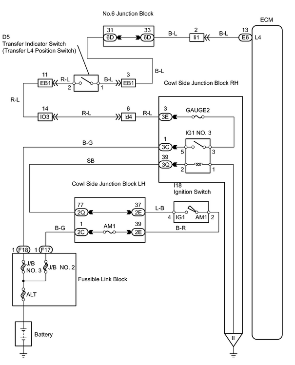
INSPECTION PROCEDURE
PROCEDURE
|
1. |
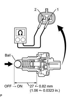
INSPECT TRANSFER INDICATOR SWITCH (L4 POSITION SWITCH) |
|
(a) Remove the transfer indicator switch. (b) Measure the resistance of the switch when pushing the ball at the tip of the switch. Standard resistance:
|
|
| NG |

|
|

|
2. |
CHECK WIRE HARNESS (TRANSFER INDICATOR SWITCH - ECM) |
(a)
Check wire harness
![2007 MY LX470 [08/2006 - ]; INTRODUCTION: HOW TO TROUBLESHOOT ECU CONTROLLED SYSTEMS: ELECTRONIC CIRCUIT INSPECTION PROCEDURE](../../../../stylegraphics/info.gif "2007 MY LX470 [08/2006 - ]; INTRODUCTION: HOW TO TROUBLESHOOT ECU CONTROLLED SYSTEMS: ELECTRONIC CIRCUIT INSPECTION PROCEDURE") .
.
| NG |
|
| OK |
|

|

|