| Last Modified: 7-3-2017 | 6.8:8.0.40 | Doc ID: RM0000013FE00QX |
| Model Year Start: 2007 | Model: LX470 | Prod Date Range: [08/2006 - ] |
| Title: A750F AUTOMATIC TRANSMISSION: CLUTCH DRUM AND INPUT SHAFT ASSEMBLY: REASSEMBLY; 2007 MY LX470 [08/2006 - ] | ||
REASSEMBLY
1. INSTALL DIRECT CLUTCH PISTON SUB-ASSEMBLY
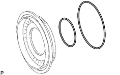
(a) Coat 2 new O-rings with ATF, and install them in the direct clutch piston.
|
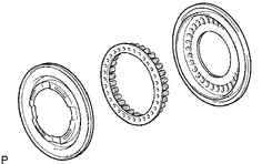
(b) Install the No. 2 clutch balancer and direct clutch return spring to the direct clutch piston. |
|
|
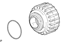
(c) Coat a new O-ring with ATF, and install them on the clutch drum sub-assembly. |
|
(d) Be careful not to damage the O-rings. Press in the direct clutch piston into the clutch drum with both hands.
|
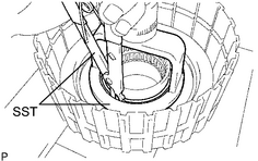
(e) Place SST on the direct clutch piston, and compress the return spring with a press. SST: 09320-89010 SST: 09350-30020 09350-07070 |
|
(f) Install the snap ring with a snap ring expander.
NOTICE:
- Be sure the end gap of the snap ring is not aligned with the spring retainer claw.
- Stop pressing when the spring sheet is lowered to the place 1 to 2 mm (0.039 to 0.078 in.) from the snap ring groove to prevent the spring sheet from being deformed.
- Do not expand the snap ring excessively.
|
(g) Set the end gap of the snap ring in the piston as shown in the illustration. |
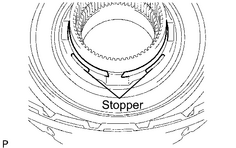
|
2. INSTALL REVERSE CLUTCH PISTON SUB-ASSEMBLY
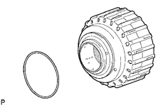
(a) Coat a new O-ring with ATF, and install it on the clutch drum.
|
(b) Coat a new O-ring with ATF, and install it on the reverse clutch piston. |
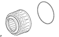
|
|
(c) Be careful not to damage the O-ring. Press in the clutch drum sub-assembly into the reverse clutch piston with both hands. |
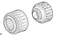
|
|
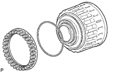
3. INSTALL REVERSE CLUTCH RETURN SPRING SUB-ASSEMBLY (a) Coat a new O-ring with ATF, and install it on the reverse clutch piston. (b) Install the reverse clutch return spring onto the reverse clutch piston. |
|
4. INSTALL NO. 3 CLUTCH BALANCER
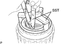
(a) Place SST on the No. 3 clutch balancer, and compress the clutch balancer with a press.
SST: 09387-00070
SST: 09350-30020
09350-07070
(b) Install the snap ring with a snap ring expander.
(c) Be sure the end gap of the snap ring is not aligned with the spring retainer claw.
NOTICE:
- Stop pressing when the spring sheet is lowered to the place 1 to 2 mm (0.039 to 0.078 in.) from the snap ring groove to prevent the spring sheet from being deformed.
- Do not expand the snap ring excessively.
|
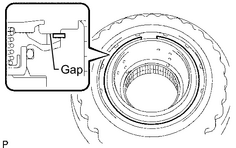
(d) Set the end gap of the snap ring in the piston as shown in the illustration. |
|
5. INSTALL DIRECT CLUTCH DISK
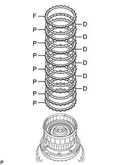
(a) Install the reverse clutch flange, 6 plates and 5 discs on the clutch drum.
Install in order:
P - P - D - P - D - P - D - P - D - P - D - P - D - F
HINT:
P = Plate, D = Disc, F = Flange
|
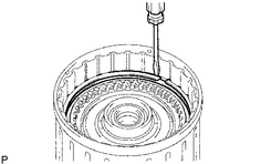
(b) Using a screwdriver, install the 2 hole snap rings on the clutch drum. |
|
6.
INSPECT PACK CLEARANCE OF DIRECT CLUTCH
![2007 MY LX470 [08/2006 - ]; A750F AUTOMATIC TRANSMISSION: CLUTCH DRUM AND INPUT SHAFT ASSEMBLY: INSPECTION+](../../../../stylegraphics/info.gif "2007 MY LX470 [08/2006 - ]; A750F AUTOMATIC TRANSMISSION: CLUTCH DRUM AND INPUT SHAFT ASSEMBLY: INSPECTION+")
|
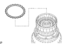
7. INSTALL REVERSE CLUTCH FLANGE (a) Install the reverse clutch flange to the clutch drum. |
|
|
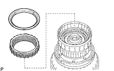
8. INSTALL REVERSE CLUTCH REACTION SLEEVE (a) Install the reverse clutch reaction sleeve, clutch cushion plate, reverse clutch flange, 5 reverse clutch discs, and 4 clutch plates to the reverse clutch hub. (b) Using a screwdriver, install the hole snap ring. |
|
9.
INSPECT PACK CLEARANCE OF REVERSE CLUTCH
10. REMOVE REVERSE CLUTCH REACTION SLEEVE
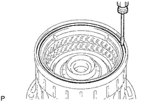
(a) Using a screwdriver, remove the snap ring from the clutch drum.
|
(b) Remove the reverse clutch reaction sleeve, clutch cushion plate, reverse clutch flange, 5 reverse clutch discs, and 4 clutch plates from the reverse clutch hub. |
|
|
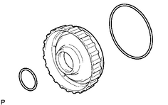
11. INSTALL FORWARD CLUTCH PISTON (a) Coat 2 new O-rings with ATF, and install them on the No. 1 forward clutch piston. |
|
12. INSTALL NO. 1 CLUTCH BALANCER
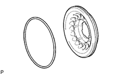
(a) Coat a new O-ring with ATF and install it on the clutch balancer.
|
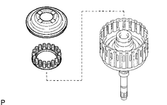
(b) Install the No. 1 clutch balancer and forward clutch return spring sub-assembly. NOTICE: Be careful not to damage the O-ring. |
|
|
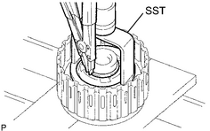
(c) Place SST on the No. 1 clutch balancer, and compress the return spring with a press. SST: 09350-30020 09350-07040 09350-07070 |
|
(d) Install the snap ring with a snap ring expander.
(e) Be sure the end gap of the snap ring is not aligned with the spring retainer claw.
NOTICE:
- Stop pressing when the spring sheet is lowered to the place 1 to 2 mm (0.039 to 0.078 in.) from the snap ring groove to prevent the spring sheet from being deformed.
- Do not expand the snap ring excessively.
|
(f) Set the end gap of the snap ring in the piston as shown in the illustration. |
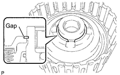
|
13. INSTALL FORWARD MULTIPLE DISC CLUTCH DISC
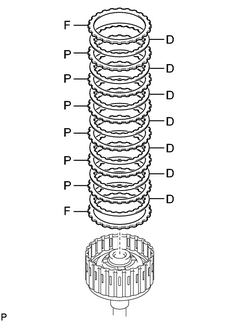
(a) Install the 2 flanges, 6 discs and 5 plates to the input shaft assembly.
Install in order:
F- D - P - D - P - D - P - D - P - D - P - D - P - D - F
HINT:
P = Plate, D = Disc, F = Flange
|
(b) Using a screwdriver, install the hole snap ring. |
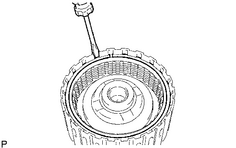
|
|
14. INSTALL INPUT SHAFT OIL SEAL RING (a) Coat the 3 oil seal rings with ATF. (b) Squeeze the ends of the 3 oil seal rings together, and then install them to the starter shaft groove. NOTICE: Do not over-spread the ring ends. HINT: After installing the oil seal rings, check that they rotate smoothly. |
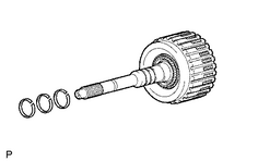
|
15.
INSPECT PACK CLEARANCE OF FORWARD CLUTCH
16. INSTALL INPUT SHAFT ASSEMBLY
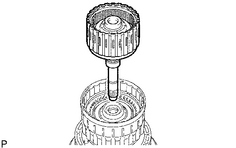
(a) Install the input shaft assembly to the clutch drum.
|
(b) Install the thrust needle roller bearing to the clutch drum. Standard thrust needle roller bearing diameter:
|
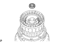
|
17. INSTALL MULTIPLE DISC CLUTCH HUB
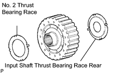
(a) Install the No. 2 thrust bearing race and input shaft thrust bearing race rear to the multiple disc clutch hub.
Standard bearing and race diameter:
|
Item |
Inside |
Outside |
|---|---|---|
|
Thrust bearing race No. 2 |
38.4 mm (1.512 in.) |
63.0 mm (2.480 in.) |
|
Input shaft bearing race rear |
22.6 mm (0.890 in.) |
60.0 mm (2.362 in.) |
|
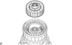
(b) Install the multiple disc clutch hub to the clutch drum. |
|
18. INSTALL FORWARD CLUTCH HUB SUB-ASSEMBLY
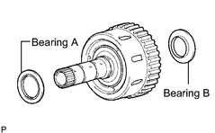
(a) Install the 2 thrust needle roller bearings to the forward clutch hub.
Standard bearing and race diameter:
|
Item |
Inside |
Outside |
|---|---|---|
|
Bearing A |
42.5 mm (1.673 in.) |
61.2 mm (2.409 in.) |
|
Bearing B |
33.3 mm (1.311 in.) |
56.6 mm (2.228 in.) |
|
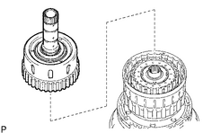
(b) Install the forward clutch hub sub-assembly to the clutch drum. |
|
|
19. INSTALL REAR CLUTCH DISC (a) Install the clutch cushion plate, reverse clutch flange, 4 plates and 5 discs to the reverse clutch hub. Install in order: D - P - D - P - D - P - D - P - D - F HINT: P = Plate, D = Disc, F = Flange |

|
|
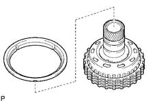
20. INSTALL REVERSE CLUTCH REACTION SLEEVE (a) Install the reverse clutch reaction sleeve to the reverse clutch hub. |
|
21. INSTALL REVERSE CLUTCH HUB SUB-ASSEMBLY
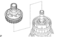
(a) Install the reverse clutch hub sub-assembly, reverse clutch reaction sleeve, clutch cushion plate, reverse clutch flange, 5 reverse clutch discs, and 4 clutch plates to the clutch drum.
|
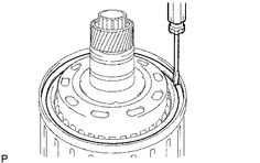
(b) Using a screwdriver, install the snap ring on the clutch drum and input shaft. |
|

|

|