-
(a) Both of following conditions are met (1 trip detection logic):
- While either of air pump or air switching valve does not operate
- Air injection control driver outputs normal signal (80% duty signal)
| Last Modified: 7-3-2017 | 6.8:8.0.40 | Doc ID: RM0000013TL00EX |
| Model Year Start: 2007 | Model: LX470 | Prod Date Range: [08/2006 - ] |
| Title: 2UZ-FE ENGINE CONTROL SYSTEM: SFI SYSTEM: P1613; Secondary Air Injection Driver Malfunction; 2007 MY LX470 [08/2006 - ] | ||
|
DTC |
P1613 |
Secondary Air Injection Driver Malfunction |
DESCRIPTION
Refer to DTC P0412
![2007 MY LX470 [08/2006 - ]; 2UZ-FE ENGINE CONTROL SYSTEM: SFI SYSTEM: P0412; Secondary Air Injection System Switching Valve "A" Circuit+](../../../../stylegraphics/info.gif "2007 MY LX470 [08/2006 - ]; 2UZ-FE ENGINE CONTROL SYSTEM: SFI SYSTEM: P0412; Secondary Air Injection System Switching Valve \"A\" Circuit+") .
.
|
DTC No. |
DTC Detection Condition |
Trouble Area |
|---|---|---|
|
P1613 |
Either of following condition (a) or (b) is met:
|
|
|
P1613 |
Both of following conditions are met (1 trip detection logic):
|
|
|
P1613 |
Air injection control driver outputs abnormal duty signal (100% duty signal) (1 trip detection logic) |
|
MONITOR DESCRIPTION
When the air injection system operation is required while the engine is warming up, the ECM transmits command signals to the Air Injection Control Driver (AID) to drive the air pump and Air Switching Valve (ASV).
AID detects an open and short in the air pump and air switching valve circuit according to the terminal voltage and sends a signal as the diagnostic information to the ECM.
If the air injection system drive circuit or the AID itself has a malfunction, the AID sends a malfunction signal (duty signal) as a diagnostic information signal to the ECM (when the system is normal, a system normal signal is sent).
The ECM sets the DTC based on the diagnostic information from the AID.
Example:
- The duty ratio of the diagnostic information signal output from AID is 0 or 100% (remains at 0 V or battery voltage).
- The duty ratio of the diagnostic signal from the AID shows an impossible ratio (other than 0, 20, 40, 60, 80, 100%).
- The AID outputs the normal signal (normal duty signal: 80%) while the system is not operating.
MONITOR STRATEGY
|
Related DTCs |
P1613: Secondary air injection system control module range check |
|
Required sensors/components |
Air injection control driver |
|
Frequency of operation |
Continuous |
|
Duration |
3 seconds |
|
MIL operation |
Immediate |
|
Sequence operation |
None |
TYPICAL ENABLING CONDITIONS
All:
|
The monitor will run whenever these DTCs are not present |
- |
Case 1:
|
Battery voltage |
8 V or more |
|
Ignition switch |
ON |
|
Starter |
OFF |
Case 2:
|
Either of following conditions is met |
Condition 1 or 2 |
|
1. Air pump |
Not operating |
|
2. Air switching valve |
Not operating |
|
Battery voltage |
8 V or more |
|
Ignition switch |
ON |
|
Starter |
OFF |
Case 3:
|
Air pump |
Operating |
|
Air switching valve |
Operating |
|
Battery voltage |
8 V or more |
|
Ignition switch |
ON |
|
Starter |
OFF |
Case 4:
|
Battery voltage |
8 V or more |
|
Ignition switch |
ON |
|
Starter |
OFF |
TYPICAL MALFUNCTION THRESHOLDS
Case 1:
|
One of the following conditions is met |
Condition 1, 2, 3 or 4 |
|
1. Diagnostic signal duty ratio from air injection control driver |
1 to 10% |
|
2. Diagnostic signal duty ratio from air injection control driver |
30% |
|
3. Diagnostic signal duty ratio from air injection control driver |
49% |
|
4. Diagnostic signal duty ratio from air injection control driver |
91 to 99% |
Case 2:
|
Diagnostic signal duty ratio from air injection control driver |
70 to 90% |
Case 3:
|
Diagnostic signal duty ratio from air injection control driver |
0% |
Case 4:
|
Diagnostic signal duty ratio from air injection control driver |
100% |
COMPONENT OPERATING RANGE
|
Diagnostic signal duty ratio from air injection control driver |
70 to 90% when secondary air injection system is operating and 0% when secondary air injection system is not operating |
WIRING DIAGRAM
Refer to DTC P0412
.
INSPECTION PROCEDURE
HINT:
The diagnostic information output from the Air Injection Control Driver (AID) can be confirmed by connecting an oscilloscope to the diagnostic information terminal of the AID. A trouble area search can be narrowed by reading the waveform on the oscilloscope when performing the AI system intrusive operation function provided in the SYSTEM CHECK.
- (a) Start the engine and warm it up.
- (b) Turn the ignition switch OFF.
- (c) Connect the intelligent tester to the CAN VIM. Then connect the CAN VIM to the DLC3.
-
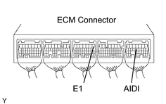
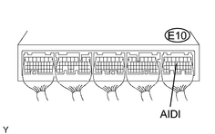
(d) Connect an oscilloscope probe to the AIDI terminal of the ECM.
- (e) Start the engine and turn the tester ON.
- (f) On the tester, enter the following menus: DIAGNOSIS / ENHANCED OBD II / SYSTEM CHECK / AIR INJ SYSTEM.
-
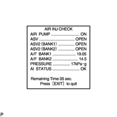
(g) On the tester, enter the following menus: DIAGNOSIS / ENHANCED OBD II / SYSTEM CHECK / AIR INJ CHECK / MANUAL / OPERATION 1 and 2.
HINT:
OPERATION 1: AP: OFF; EASV: CLOSE; ASV1: CLOSE; ASV2: OFF
OPERATION 2: AP: ON; EASV: OPEN; ASV1: OPEN; ASV2: OPEN
-
(h) Monitor the voltage output of the AID (duty ratio signal).
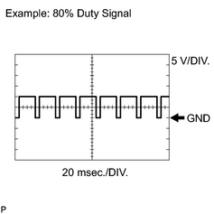
Oscilloscope range:
Item
Content
Terminal
CH1: AIDI - E1
Equipment Setting
5 V/DIV., 20 to 40 msec./DIV.
Condition
Idling
NOTICE:
-
This AIR INJECTION CHECK only allows technicians to operate the AI system for 5 seconds. Furthermore, the check can be performed 4 times a trip. If the test is repeated, intervals of at least 30 seconds are required between checks.
While the AI system operation using the intelligent tester is prohibited, the tester displays the prohibition (WAIT or ERROR). If ERROR (AI STATUS NG) is displayed on the tester, stop the engine for 10 minutes and then try again.
- Performing the AIR INJ CHECK over and over again may cause damage in the secondary air injection system. If necessary, wait several minutes between tests to prevent overheating the system.
- When performing the AIR INJ CHECK operation after the battery cable has been reconnected, wait for 7 minutes with the ignition switch turned ON or the engine running.
- Turn the ignition switch OFF when the AIR INJ CHECK operation finishes.
|
AID Diagnostic Signal Waveform |
ECM Command |
DTC (ECM Output) |
Suspected Trouble Area |
|---|---|---|---|
|
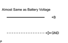
100% Duty Ratio See waveform 1 |
Any Air Injection (AI) System operation |
P1613 |
|
|
0% Duty Ratio See waveform 2 |
AI System: ON (Air pump ON, ASV ON) |
P1613 |
|
|
AI System: OFF (Air pump OFF, ASV OFF) |
- |
|
|
|
20% Duty Ratio See waveform 3 |
Air Pump: ON |
P0418 |
|
|
Air Pump: OFF |
P0418 |
|
|
|
40% Duty Ratio See waveform 4 |
ASV: ON |
P0412 |
|
|
ASV: OFF |
P0412 |
|
|
|
80% Duty Ratio See waveform 5 |
AI System: OFF (Air pump OFF, ASV OFF) |
P1613 |
|
|
AI System: ON (Air pump ON, ASV ON) |
- |
|
|
|
Excluding Above (excluding 0, 20, 40, 80, 100% duty) |
- |
P1613 |
|
|
1. Waveform 1
|
|
|
2. Waveform 2
|
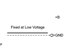
|
|
3. Waveform 3
|
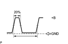
|
|
4. Waveform 4
|
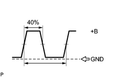
|
|
5. Waveform 5
|
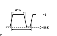
|
HINT:
- Using the AIR INJ CHECK operation of the SYSTEM CHECK provided in the intelligent tester function, conditions for air fuel ratio and pressure in the secondary air injection system passage can be checked while the secondary air injection system is operating. It helps technicians to troubleshoot the system when it is malfunctioning.
- Read freeze frame data using the intelligent tester. Freeze frame data records the engine conditions when malfunctions are detected. When troubleshooting, freeze frame data can help determine if the vehicle was moving or stationary, if the engine was warmed up or not, if the air fuel ratio was lean or rich, and other data from the time the malfunction occurred.
PROCEDURE
|
1. |
CHECK ANY OTHER DTCS OUTPUT (IN ADDITION TO DTC P1613) |
(a) Connect the intelligent tester to the CAN VIM. Then connect the CAN VIM to the DLC3.
(b) Turn the ignition switch ON and turn the tester ON.
(c) Enter the following menus: DIAGNOSIS / ENHANCED OBD II / DTC INFO / CURRENT CODES.
(d) Read DTCs.
|
Display (DTC Output) |
Proceed to |
|---|---|
|
P1613 |
A |
|
P1613 and other DTCs |
B |
HINT:
If any DTCs other than P1613 are output, troubleshoot those DTCs first.
| B |

|
|

|
2. |
PERFORM ACTIVE TEST USING INTELLIGENT TESTER (AIDI VOLTAGE) |
|
(a) Start the engine and warm it up. (b) Turn the ignition switch OFF. (c) Connect the intelligent tester to the CAN VIM. Then connect the CAN VIM to the DLC3. (d) Turn the ignition switch ON and turn the tester ON. (e) Start the engine. (f) Enter the following menus: DIAGNOSIS / ENHANCED OBD II / SYSTEM CHECK / AIR INJ CHECK / AUTOMATIC. NOTICE:
(g) Measure voltage between terminal E10-13 (AIDI) of the ECM connector and body ground when the air injection system is ON and OFF.
|
|
| B |
|
| C |
|
|
|
3. |
INSPECT ECM (AIRP AND AIRV VOLTAGE) |
|
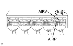
(a) Turn the ignition switch ON. (b) Measure voltage between terminal E10-25 (AIRP), E10-4 (AIRV) of the ECM connector and body ground. Standard voltage:
|
|
| NG |
|
|
|
4. |
CHECK HARNESS AND CONNECTOR (ECM - AIR INJECTION CONTROL DRIVER, AIR INJECTION CONTROL DRIVER - BODY GROUND) |
(a)
Check the harness and connector
.
| NG |
|
| OK |
|
|
5. |
CHECK POWER SOURCE OF AIR INJECTION CONTROL DRIVER |
|
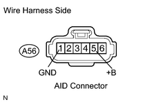
(a) Disconnect the A56 Air Injection Control Driver (AID) connector. (b) Turn the ignition switch ON. (c) Measure the voltage between the terminal +B (A56-5) and GND (A56-1) of the AID connector. Standard voltage:
|
|
| NG |
|
|
|
6. |
INSPECT AIR INJECTION CONTROL DRIVER (DI TERMINAL VOLTAGE) |
|
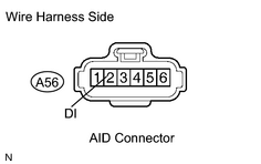
(a) Disconnect the A56 AID connector. (b) Turn the ignition switch ON. (c) Measure the voltage between the terminal A56-2 (DI) of the AID connector and body ground. Standard voltage:
(d) Reconnect the AID connector. |
|
| OK |
|
|
|
7. |
CHECK HARNESS AND CONNECTOR (ECM - AIR INJECTION CONTROL DRIVER) |
(a)
Check the harness and connector
.
| NG |
|
| OK |
|
|
8. |
CHECK HARNESS AND CONNECTOR (AIR INJECTION DRIVER - BODY GROUND) |
|
(a) Disconnect the A56 AID connector. |
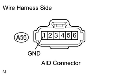
|
(b) Measure the resistance between the terminal GND (A56-1) of the AID connector and body ground.
Standard resistance:
|
Tester Connection |
Specified Condition |
|---|---|
|
A56-1 (GND) - Body ground |
Below 1 Ω |
(c) Reconnect the AID connector.
| NG |
|
|
|
9. |
REPLACE AIR INJECTION CONTROL DRIVER |
(a)
Replace the AID
.
|
|
10. |
CHECK WHETHER DTC OUTPUT RECURS (DTC P1613) |
(a) Connect the intelligent tester to the CAN VIM. Then connect the CAN VIM to the DLC3.
(b) Turn the ignition switch ON and turn the tester ON.
(c)
Clear the DTCs
.
(d) Start the engine.
(e) Perform ACTIVE TEST to operate the air injection system.
Enter the following menus: DIAGNOSIS / ENHANCED OBD II / SYSTEM CHECK / AIR INJ CHECK / AUTOMATIC.
(f) After operating the secondary air injection system, confirm the pending codes of the secondary air injection system by entering the following menus: DIAGNOSIS / ENHANCED OBD II / DTC INFO / PENDING CODES.
NOTICE:
- When performing the AIR INJ CHECK operation after the battery cable has been reconnected, wait for 7 minutes with the ignition switch turned ON or the engine running.
- Turn the ignition switch OFF when the AIR INJ CHECK operation finishes.
OK:
DTC P1613 for the secondary air injection system is not output.
| NG |
|
| OK |
|

|

|