- Open in driver side squib circuit
- Driver side squib malfunction
- Spiral cable malfunction
- Center airbag sensor assembly malfunction
| Last Modified: 7-3-2017 | 6.8:8.0.40 | Doc ID: RM0000017PM005X |
| Model Year Start: 2007 | Model: LX470 | Prod Date Range: [08/2006 - ] |
| Title: SUPPLEMENTAL RESTRAINT SYSTEM: AIRBAG SYSTEM: B0101/14; Open in Driver Side Squib Circuit; 2007 MY LX470 [08/2006 - ] | ||
|
DTC |
B0101/14 |
Open in Driver Side Squib Circuit |
DESCRIPTION
The driver side squib circuit consists of the center airbag sensor, the spiral cable and the steering wheel pad.
The circuit instructs the SRS to deploy when deployment conditions are met.
DTC B0101/14 is recorded when an open is detected in the driver side squib circuit.
|
DTC No. |
DTC Detection Condition |
Trouble Area |
|---|---|---|
|
B0101/14 |
|
|
WIRING DIAGRAM
Refer to DTC B0100/13
![2007 MY LX470 [08/2006 - ]; SUPPLEMENTAL RESTRAINT SYSTEM: AIRBAG SYSTEM: B0100/13; Short in Driver Side Squib Circuit+](../../../../stylegraphics/info.gif "2007 MY LX470 [08/2006 - ]; SUPPLEMENTAL RESTRAINT SYSTEM: AIRBAG SYSTEM: B0100/13; Short in Driver Side Squib Circuit+") .
.
INSPECTION PROCEDURE
PROCEDURE
|
1. |
CHECK DRIVER SIDE SQUIB CIRCUIT |
|
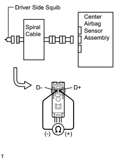
(a) Turn the ignition switch OFF. (b) Disconnect the negative (-) terminal cable from the battery, and wait for at least 90 seconds. (c) Disconnect the connectors from the C32 center airbag sensor and the steering wheel pad. (d) Measure the resistance between D+ and D- of the orange connector on the steering wheel pad (driver side squib) side between the center airbag sensor and the steering wheel pad (driver side squib). Standard resistance: Below 1 Ω |
|
| NG |

|
|

|
2. |
CHECK CENTER AIRBAG SENSOR ASSEMBLY |
|
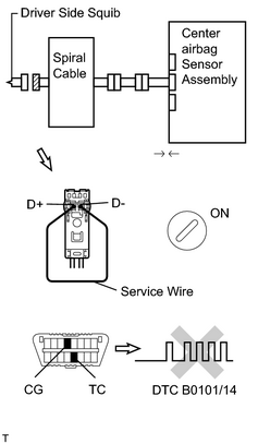
(a) Connect the connector to the center airbag sensor. (b) Using a service wire, connect D+ and D- of the orange connector on the steering wheel pad (driver side squib) side between the center airbag sensor and the steering wheel pad (driver side squib). (c) Connect the negative (-) terminal cable to the battery, and wait at least for 2 seconds. (d) Turn the ignition switch ON, and wait at least for 10 seconds. (e)
Clear the DTC stored in memory
(f) Turn the ignition switch OFF, and wait at least for 10 seconds. (g) Turn the ignition switch ON, and wait at least for 10 seconds. (h)
Check the DTC
OK: DTC B0101/14 is not output. HINT: Codes other than code B0101/14 may be output at this time, but they are not relevant to this check. |
|
| NG |
|
|
|
3. |
CHECK DRIVER SIDE SQUIB |
|
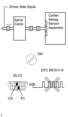
(a) Turn the ignition switch OFF. (b) Disconnect the negative (-) terminal cable from the battery, and wait at least for 90 seconds. (c) Connect the steering wheel pad (driver side squib) to the spiral cable. (d) Connect the negative (-) terminal cable to the battery, and wait at least for 2 seconds. (e) Turn the ignition switch ON, and wait at least for 10 seconds. (f)
Clear the DTC stored in memory
(g) Turn the ignition switch OFF, and wait at least for 10 seconds. (h) Turn the ignition switch ON, and wait at least for 10 seconds. (i)
Check the DTC
OK: DTC B0101/14 is not output. HINT: Codes other than code B0101/14 may be output at this time, but they are not relevant to this check. |
|
| NG |
|
| OK |
|
|
4. |
CHECK SPIRAL CABLE |
|
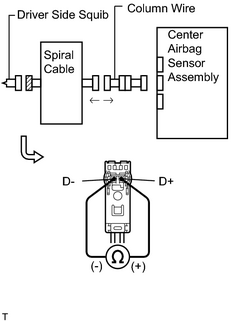
(a) Disconnect the A29 spiral cable connector from the column wire. (b) Measure the resistance between D+ and D- of the orange spiral cable connector on the steering wheel pad (driver side squib) side. Standard resistance: Below 1 Ω |
|
| NG |
|
|
|
5. |
CHECK COLUMN WIRE |
|
(a) Disconnect the column wire connector from the dash wire. (b) Measure the resistance between D+ and D- of the A29 column wire connector on the spiral cable side. Standard resistance: Below 1 Ω |
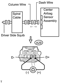
|
| NG |
|
|
|
6. |
CHECK DASH WIRE |
|
(a) Measure the resistance between D+ and D- of the II4 dash wire connector on the column wire side. Standard resistance: Below 1 Ω |
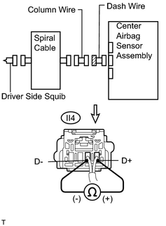
|
| NG |
|
| OK |
|

|

|