- Power window regulator master switch assembly
- Power window regulator switch assembly (front RH door ECU)
- Power window regulator switch assembly (rear LH door ECU)
- Power window regulator switch assembly (rear RH door ECU)
- Multiplex network body ECU (main)
- Wire harness
| Last Modified: 7-3-2017 | 6.8:8.0.40 | Doc ID: RM0000017WT006X |
| Model Year Start: 2007 | Model: LX470 | Prod Date Range: [08/2006 - ] |
| Title: MULTIPLEX COMMUNICATION: MULTIPLEX COMMUNICATION SYSTEM: B1214,B1215; Short to B+ in Door System Communication Bus Malfunction; 2007 MY LX470 [08/2006 - ] | ||
|
DTC |
B1214 |
Short to B+ in Door System Communication Bus Malfunction |
|
DTC |
B1215 |
Short to GND in Door System Communication Bus Malfunction |
DESCRIPTION
- This DTC is output when a +B or GND short occurs on the door system communication bus.
|
DTC No. |
DTC Detection Condition |
Trouble Area |
|---|---|---|
|
B1214 |
Door system communication circuit and +B battery system short |
|
|
B1215 |
Door system communication circuit and body ground short |
|
WIRING DIAGRAM
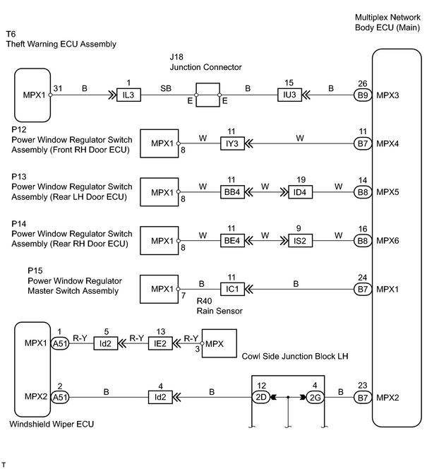
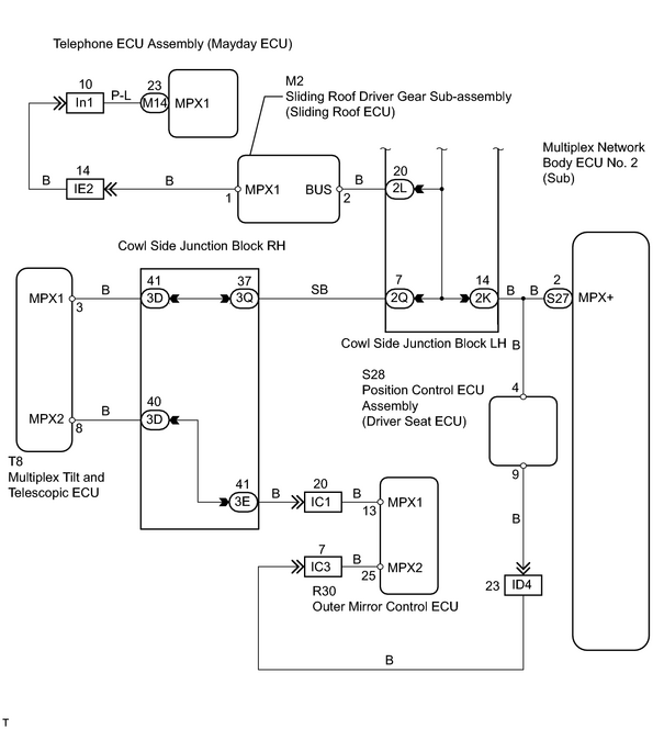
INSPECTION PROCEDURE
PROCEDURE
|
1. |
CHECK COMMUNICATION CIRCUIT INSIDE ECU |
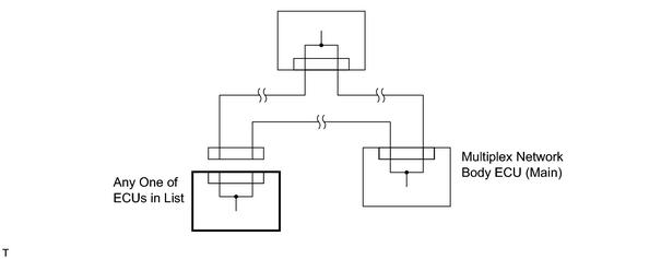
(a) Disconnect the following ECU connectors in the order shown in the list below.
HINT:
Before disconnecting the next connector, be sure that the disconnected ECU connector is reconnected.
(b) Check the DTC whenever each connector is disconnected.
|
Disconnect ECU connector |
Connector No. |
|---|---|
|
Power window regulator master switch assembly |
P15 |
|
Power window regulator switch assembly (Front RH door ECU) |
P12 |
|
Power window regulator switch assembly (Rear LH door ECU) |
P13 |
|
Power window regulator switch assembly (Rear RH door ECU) |
P14 |
OK:
DTC B1214 or B1215 is not output.
| OK |

|
REPLACE CORRESPONDING ECU (IF DTC IS NOT OUTPUT WHEN CONNECTOR IS DISCONNECTED, ECU IS DEFECTIVE) |
|

|
2. |
CHECK FOR SHORT CIRCUIT |
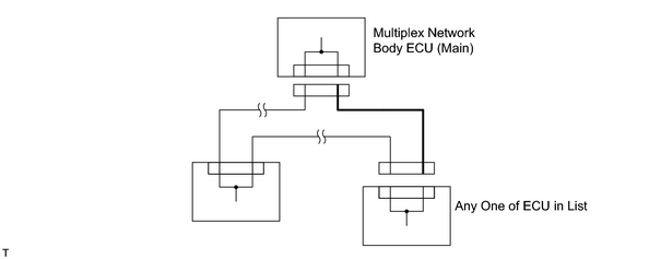
(a) Disconnect the following ECU connectors in the order shown in the list below.
HINT:
Before disconnecting the next connector, be sure to reconnect the ECU connector that is disconnected.
(b) Check whether or not there is +B short and GND short between the connectors below.
|
Disconnect ECU connector |
Connector No. |
|---|---|
|
Multiplex network body ECU (Main) Power window regulator master switch assembly |
B7 P15 |
|
Multiplex network body ECU (Main) Power window regulator switch assembly (Front RH door ECU) |
B7 P12 |
|
Multiplex network body ECU (Main) Power window regulator switch assembly (Rear LH door ECU) |
B8 P13 |
|
Multiplex network body ECU (Main) Power window regulator switch assembly (Rear RH door ECU) |
B8 P14 |
OK:
No +B short and GND short.
| NG |
|
| OK |
|

|

|