| Last Modified: 7-3-2017 | 6.8:8.0.40 | Doc ID: RM00000185P001X |
| Model Year Start: 2007 | Model: LX470 | Prod Date Range: [08/2006 - ] |
| Title: ENGINE IMMOBILISER: ENGINE IMMOBILISER SYSTEM: Power Source Circuit; 2007 MY LX470 [08/2006 - ] | ||
|
Power Source Circuit |
DESCRIPTION
This circuit provides power to operate the transponder key ECU assembly.
WIRING DIAGRAM
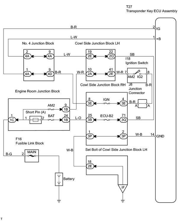
INSPECTION PROCEDURE
PROCEDURE
|
1. |
INSPECT FUSE (IGN, ECU-B2, AM2, BAT) |
(a) Remove the IGN and ECU-B2 fuses from the cowl side junction block RH.
(b) Remove the AM2 and BAT fuses from the engine room junction block.
(c) Measure the resistance of the fuses.
Standard resistance:
Below 1 Ω
| NG |

|
|

|
2. |
CHECK WIRE HARNESS (TRANSPONDER KEY ECU ASSEMBLY - BATTERY AND BODY GROUND) |
(a) Disconnect the T27 ECU connector.
(b) Measure the resistance and voltage of the wire harness side connector.
Standard resistance:
|
Tester Connection |
Specified Condition |
|---|---|
|
T27-14 (GND) - Body ground |
Below 1 Ω |
Standard voltage:
|
Tester Connection |
Condition |
Specified Condition |
|---|---|---|
|
T27-1 (+B) - T27-14 (GND) |
Always |
10 to 14 V |
|
T27-2 (IG) - T27-14 (GND) |
Ignition switch OFF |
Below 1 V |
|
Ignition switch ON |
10 to 14 V |
| NG |
|
| OK |
|
PROCEED TO NEXT CIRCUIT INSPECTION SHOWN ON PROBLEM SYMPTOMS TABLE |

|

|