| Last Modified: 7-3-2017 | 6.8:8.0.40 | Doc ID: RM000001860001X |
| Model Year Start: 2007 | Model: LX470 | Prod Date Range: [08/2006 - ] |
| Title: ENGINE IMMOBILISER: ENGINE IMMOBILISER SYSTEM: Security Indicator Light Circuit; 2007 MY LX470 [08/2006 - ] | ||
|
Security Indicator Light Circuit |
WIRING DIAGRAM
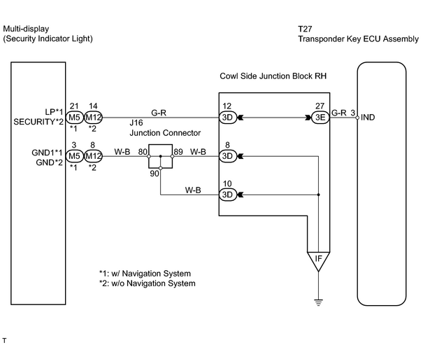
INSPECTION PROCEDURE
PROCEDURE
|
1. |
INSPECT TRANSPONDER KEY ECU ASSEMBLY TERMINAL VOLTAGE |
(a) Select the ACTIVE TEST, use the intelligent tester to generate a control command, and then check the security indicator light function.
Transponder key ECU assembly:
|
Item |
Test Details |
Diagnostic Note |
|---|---|---|
|
SECURITY INDIC |
Turn security indicator ON/OFF |
- |
|
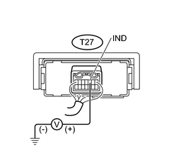
(b) Measure the voltage of the T27 ECU connector. |
|
Standard voltage:
w/ Navigation system
w/o Navigation system
|
Tester Connection |
Security Indicator Light Condition |
Specified Condition |
|---|---|---|
|
T27-3 (IND) - Body ground |
ON |
8 to 10 V |
|
OFF |
Below 1 V |
|
Tester Connection |
Security Indicator Light Condition |
Specified Condition |
|---|---|---|
|
T27-3 (IND) - Body ground |
ON |
3 to 6 V |
|
OFF |
Below 1 V |
| NG |

|
Go to NAVIGATION SYSTEM (w/ NAVIGATION), MULTI-DISPLAY SYSTEM (w/o NAVIGATION SYSTEM) |
| OK |
|
PROCEED TO NEXT CIRCUIT INSPECTION SHOWN ON PROBLEM SYMPTOMS TABLE |

|

|