| Last Modified: 7-3-2017 | 6.8:8.0.40 | Doc ID: RM00000188I005X |
| Model Year Start: 2007 | Model: LX470 | Prod Date Range: [08/2006 - ] |
| Title: 2UZ-FE STARTING: STARTER: INSTALLATION; 2007 MY LX470 [08/2006 - ] | ||
INSTALLATION
|
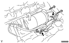
1. INSTALL STARTER ASSEMBLY (a) Install the starter with the 2 bolts. Torque: 39 N·m {400 kgf·cm, 29ft·lbf} (b) Connect the engine wire protector with the bolt. (c) Connect the starter cable with the nut. Torque: 9.8 N·m {100 kgf·cm, 86in·lbf} (d) Connect the starter connector. |
|
2.
INSTALL AIR SWITCHING VALVE ASSEMBLY
![2007 MY LX470 [08/2006 - ]; 2UZ-FE EMISSION CONTROL: AIR PUMP: INSTALLATION+](../../../../stylegraphics/info.gif "2007 MY LX470 [08/2006 - ]; 2UZ-FE EMISSION CONTROL: AIR PUMP: INSTALLATION+")
3.
INSTALL AIR PUMP ASSEMBLY WITH BRACKET
4. INSTALL REAR WATER BY-PASS JOINT
(a) Install 2 new gaskets to the cylinder head.
(b) Install the 4 nuts holding the water by-pass joint to the cylinder heads. Alternately tighten the nuts.
Torque:
18 N·m {185 kgf·cm, 13ft·lbf}
5. INSTALL WATER BY-PASS PIPE SUB-ASSEMBLY
(a) Install a new O-ring to the water by-pass pipe.
(b) Apply soapy water to the O-ring.
(c) Push the water by-pass pipe end into the pipe hole of the water pump.
(d) Install the water by-pass pipe with the nut.
Torque:
18 N·m {185 kgf·cm, 13ft·lbf}
(e) Install the wire clamp to the bracket of the water by-pass pipe.
6. INSTALL INTAKE MANIFOLD ASSEMBLY
(a) Install 2 new gaskets to the cylinder head.
(b) Install the intake manifold with the 4 bolts and 2 nuts.
Torque:
18 N·m {185 kgf·cm, 13ft·lbf} for bolt
18 N·m {185 kgf·cm, 13ft·lbf} for nut
|
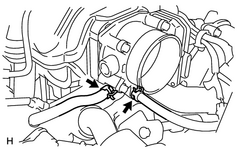
7. CONNECT WATER BY-PASS HOSE |
|
8. CONNECT NO. 7 WATER BY-PASS HOSE
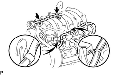
9. INSTALL ENGINE WIRE
|
(a) Install the 3 bolts and connect the engine wire. Torque: 8.2 N·m {83 kgf·cm, 72in·lbf} |
|
(b) Connect the engine coolant temperature sensor connector.
(c) Connect the throttle position sensor and control motor connector.
(d) Connect the 8 fuel injector connectors.
10.
INSTALL VACUUM CONTROL VALVE SET
11.
INSTALL PURGE VSV
12.
CONNECT VENTILATION HOSE
13.
CONNECT NO. 2 FUEL HOSE
14.
CONNECT FUEL HOSE
15.
INSTALL INTAKE AIR CONNECTOR
16. ADD ENGINE COOLANT
17. CHECK FOR ENGINE COOLANT LEAKS
(a)
Check for engine coolant leaks
.
18. CHECK FOR FUEL LEAKS
19.
INSTALL V-BANK COVER SUB-ASSEMBLY
20. PERFORM INITIALIZATION
(a)
Perform initialization
.
NOTICE:
Certain systems need to be initialized after disconnecting the cable from the negative (-) battery terminal.

|

|