| Last Modified: 7-3-2017 | 6.8:8.0.40 | Doc ID: RM00000188J005X |
| Model Year Start: 2007 | Model: LX470 | Prod Date Range: [08/2006 - ] |
| Title: 2UZ-FE STARTING: STARTER: INSPECTION; 2007 MY LX470 [08/2006 - ] | ||
INSPECTION
1. INSPECT STARTER ARMATURE ASSEMBLY
(a) Measure the resistance.
|
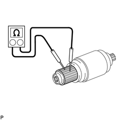
(1) Measure the resistance between the segments of the commutator. Standard resistance: Below 1 Ω If the result is not as specified, replace the starter armature assembly. |
|
|
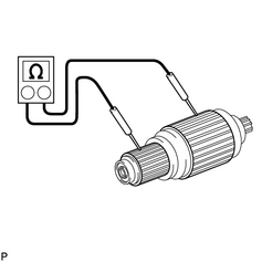
(2) Measure the resistance between a segment of the commutator and armature coil core. Standard resistance: 10 kΩ or higher If the result is not as specified, replace the armature assembly. |
|
|
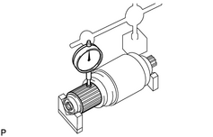
(b) Inspect circle runout. (1) Place the armature on V-blocks. (2) Using a dial gauge, measure the circle runout. Maximum circle runout: 0.05 mm (0.0020 in.) If the circle runout is greater than the maximum, correct it on a lathe. |
|
|
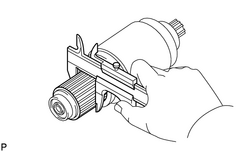
(c) Using a vernier caliper, measure the commutator diameter. Standard undercut depth: 35.0 mm (1.378 in.) Minimum undercut depth: 34.0 mm (1.339 in.) If the diameter is less than the minimum, replace the armature assembly. |
|
|
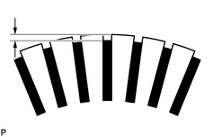
(d) Measure the undercut depth of the commutator. Standard undercut depth: 0.7 mm (0.028 in.) Minimum undercut depth: 0.2 mm (0.008 in.) If the undercut depth is less than the minimum, correct it with a hacksaw blade. |
|
(e) Inspect the bearings.
(1) Check that the bearing rotate smoothly.
If the diameter is less than the minimum, replace the armature assembly.
2. INSPECT STARTER YOKE ASSEMBLY
|
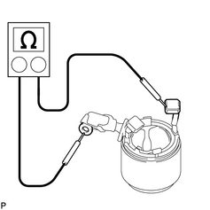
(a) Inspect the field coil for an open circuit. (1) Measure the resistance between the lead wire and field coil brush lead. Standard resistance: Below 1 Ω If the result is not as specified, replace the starter yoke assembly. |
|
|
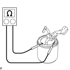
(b) Inspect the shunt coil for an open circuit. (1) Measure the resistance between the shunt coil terminals. Standard resistance: 1.5 to 1.9 Ω at 20°C (68°F) If the result is not as specified, replace the starter yoke assembly. |
|
3. INSPECT BRUSH
|
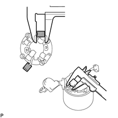
(a) Using a vernier caliper, measure the brush length. Standard length: 15.0 mm (0.591 in.) Minimum length: 9.0 mm (0.354 in.) If the length is less than the minimum, replace the starter brush holder assembly and starter yoke assembly. |
|
4. INSPECT STARTER BRUSH HOLDER ASSEMBLY
|
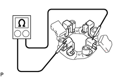
(a) Inspect the brush insulation. (1) Using an ohmmeter, measure the resistance between the positive and negative brush holders. Standard resistance: 10 kΩ or higher If the result is not as specified, replace the brush holder assembly. |
|
|
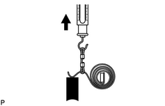
(b) Take the pull scale reading the instant the brush spring separates from the brush. Standard spring installed load: 21.5 to 27.5 N (2.2 to 2.8 kgf*cm, 4.8 to 6.2 in.*lbf) Minimum spring installed load: 12.7 (1.3 kgf*cm, 2.9 in.*lbf) If the spring load is less than the minimum, replace the brush spring. |
|
5. INSPECT STARTER CLUTCH SUB-ASSEMBLY
|
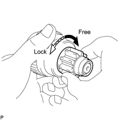
(a) Rotate the pinion gear clockwise, and check that it turns freely. Try to rotate the pinion gear counterclockwise and check that it locks. If necessary, replace the clutch. |
|
6. INSPECT MAGNET STARTER SWITCH ASSEMBLY
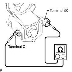
(a) Check if the pull-in coil has an open circuit.
|
(1) Measure the resistance between terminals 50 and C. Standard resistance: Below 2 Ω If the result is not as specified, replace the magnet starter switch assembly. |
|
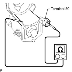
(b) Check if the hold-in coil has an open circuit.
|
(1) Measure the resistance between terminal 50 and the switch body. Standard resistance: Below 1 Ω If the result is not as specified, replace the magnet starter switch assembly. |
|

|

|