| Last Modified: 7-3-2017 | 6.8:8.0.40 | Doc ID: RM0000018CY003X |
| Model Year Start: 2007 | Model: LX470 | Prod Date Range: [08/2006 - ] |
| Title: HF2A TRANSFER: TRANSFER ASSEMBLY: DISASSEMBLY; 2007 MY LX470 [08/2006 - ] | ||
DISASSEMBLY
1. REMOVE BREATHER HOSE
2. REMOVE VEHICLE SPEED SENSOR DRIVEN GEAR
(a) Remove the bolt and driven gear.
|
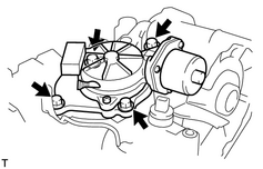
3. REMOVE MOTOR ACTUATOR (a) Remove the 4 bolts and motor actuator. |
|
|
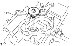
4. REMOVE OUTPUT GEAR |
|
|
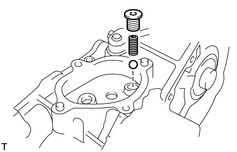
5. REMOVE SCREW PLUG (a) Using a T40 "torx" socket, remove the screw plug. |
|
6. REMOVE SPRING
(a) Using a magnetic finger, remove the spring.
7. REMOVE BALL
(a) Using a magnetic finger, remove the ball.
8. REMOVE TRANSFER INDICATOR SWITCH
(a) Remove the 3 indicator switches and 3 gaskets.
|
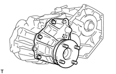
9. REMOVE FRONT TRANSFER EXTENSION HOUSING SUB-ASSEMBLY (a) Remove the 6 bolts and extension housing. HINT: If necessary, tap the extension housing lightly with a plastic-faced hammer. |
|
|
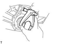
10. REMOVE CLUTCH SLEEVE WITH NO. 2 SHIFT FORK SHAFT AND NO. 2 SHIFT FORK |
|
|
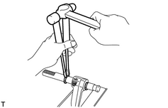
11. SEPARATE NO. 2 SHIFT FORK SHAFT AND NO. 2 SHIFT FORK (a) Using 2 screwdrivers and a hammer, tap out the 3 snap rings from the No. 2 shift fork shaft. (b) Separate the No. 2 shift fork shaft and No. 2 shift fork. |
|
|
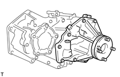
12. REMOVE REAR TRANSFER EXTENSION HOUSING SUB-ASSEMBLY (a) Remove the 9 bolts and extension housing. HINT: If necessary, tap the extension housing lightly with a plastic-faced hammer. |
|
13. REMOVE ADJUSTING SHIM
(a) Remove the adjusting shims.
|
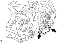
14. REMOVE OIL STRAINER ASSEMBLY (a) Remove the 2 bolts and oil strainer. |
|
15. REMOVE CASE COVER
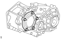
(a) Remove the 5 bolts.
|
(b) Using a brass bar and hammer, tap the case cover and remove it. |
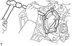
|
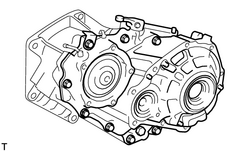
16. SEPARATE FRONT CASE AND REAR CASE
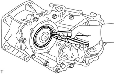
(a) Using a snap ring expander, remove the snap ring from the rear case.
|
(b) Remove the 8 bolts. |
|
(c) Using a brass bar and hammer, tap the rear case and separate it.
|
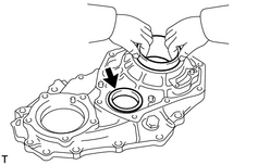
17. REMOVE BEARING RACE (a) Remove the 2 bearing races from the rear case. |
|
|
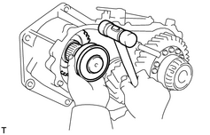
18. REMOVE INPUT SHAFT SUB-ASSEMBLY (a) Using a plastic-faced hammer, remove the input shaft from the front case. |
|
|
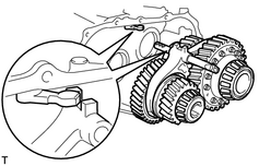
19. REMOVE IDLER GEAR ASSEMBLY WITH CENTER DIFFERENTIAL ASSEMBLY, NO. 1 SHIFT FORK SHAFT AND NO. 1 SHIFT FORK (a) Remove the idler gear with center differential, No. 1 shift fork shaft and No. 1 shift fork from the front case. |
|
|
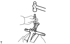
20. SEPARATE NO. 1 SHIFT FORK SHAFT AND NO. 1 SHIFT FORK (a) Using a pin punch and hammer, tap out the slotted spring pin. (b) Separate the No. 1 shift fork and No. 1 shift fork shaft. |
|
|
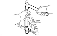
21. REMOVE OUTER SHIFT LEVER AND INNER SHIFT LEVER (a) Remove the nut and washer from the outer shift lever. (b) Using a brass bar, hammer and socket wrench, tap out the lever lock pin. (c) Remove the outer shift lever, washer and inner shift lever from the front case. |
|
|
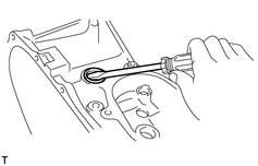
22. REMOVE INNER SHIFT LEVER OIL SEAL (a) Using a screwdriver, pry out the oil seal from the front case. |
|
|
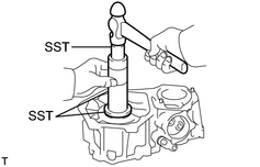
23. REMOVE INPUT SHAFT OIL SEAL (a) Using SST and a hammer, tap out the oil seal. SST: 09316-60011 09316-00011 |
|
|
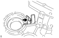
24. REMOVE OIL RECEIVER (a) Remove the bolt and oil receiver from the front case. |
|
25. REMOVE BEARING RACE
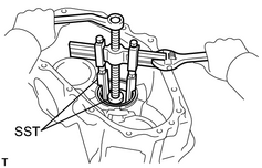
(a) Using SST, remove the bearing race (for the idler gear).
SST: 09950-40011
09951-04020
09952-04010
09953-04030
09954-04010
09955-04061
09957-04010
SST: 09950-60010
09951-00320
|
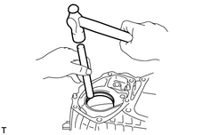
(b) Using a brass bar and hammer, tap out the bearing race (for the output shaft) from the front case. |
|

|

|