| Last Modified: 7-3-2017 | 6.8:8.0.40 | Doc ID: RM0000018DJ005X |
| Model Year Start: 2007 | Model: LX470 | Prod Date Range: [08/2006 - ] |
| Title: BRAKE: BRAKE PEDAL: ON-VEHICLE INSPECTION; 2007 MY LX470 [08/2006 - ] | ||
ON-VEHICLE INSPECTION
|
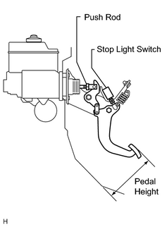
1. CHECK BRAKE PEDAL HEIGHT Standard pedal height from asphalt sheet: 183.7 to 193.7 mm (7.232 to 7.626 in.) If the pedal height is not as specified, adjust it. |
|
2. ADJUST BRAKE PEDAL HEIGHT
(a)
Remove the scuff plate, cowl side trim, No. 1 lower panel, LH lower panel and No. 2 heater to register duct
![2007 MY LX470 [08/2006 - ]; STEERING COLUMN: STEERING COLUMN ASSEMBLY: COMPONENTS](../../../../stylegraphics/info.gif "2007 MY LX470 [08/2006 - ]; STEERING COLUMN: STEERING COLUMN ASSEMBLY: COMPONENTS") .
.
(b)
Remove the steering wheel pad, No. 2 and No. 3 steering wheel lower covers, steering wheel, combination switch, upper and lower column covers, steering column and thrust stopper
.
(c) Disconnect the connector from the stop light switch.
(d) loosen the stop light switch lock nut and remove the stop light switch.
(e) Loosen the push rod lock nut.
(f) Adjust the pedal height by turning the pedal push rod.
(g) Tighten the push rod lock nut.
Torque:
25 N·m {260 kgf·cm, 19ft·lbf}
(h) Install the stop light switch.
(i) Connect the connector to the stop light switch.
(j) Push in the brake pedal 5 to 15 mm (0.20 to 0.59 in.), and turn the stop light switch to lock the nut in the position where the stop light goes off.
(k) After installation, push in the brake pedal 5 to 15 mm (0.20 to 0.59 in.), check that stop light lights up.
(l) After adjusting the pedal height, check the pedal free play.
(m)
Install the thrust stopper, steering column, upper and lower column covers, combination switch, steering wheel, No. 2 and No. 3 steering wheel lower covers, and steering wheel pad
.
(n)
Install the No. 2 heater to register duct, LH lower panel, No. 1 lower panel, cowl side trim and scuff plate
.
|
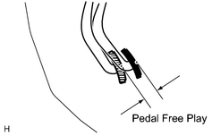
3. CHECK BRAKE PEDAL FREE PLAY (a) Stop the engine and depress the brake pedal more than 40 times until there is no more pressure left in the booster. (b) Push in the pedal by hand until the second point of resistance begins to be felt, then measure the distance, as shown in the illustration. Standard pedal free play: 1.0 to 6.0 mm (0.039 to 0.236 in.) If the distance is not as specified, check the stop light switch clearance. If the distance is as specified, then troubleshoot the brake system. Standard stop light switch clearance: 1.9 mm (0.075 in.) HINT: The free play to the first point of resistance is due to the play between the clevis, pedal link and pin. It is 1.0 to 6.0 mm (0.039 to 0.236 in.) on the pedal. |
|
|
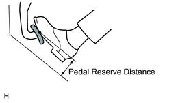
4. CHECK BRAKE PEDAL RESERVE DISTANCE (a) Remove the floor carpet. (b) Release the parking brake. (c) With the engine running, depress the pedal and measure the pedal reserve distance, as shown in the illustration. Standard pedal reserve distance at 490 N (50 kgf, 110.1 lbf): More than 116 mm (4.57 in.) If the reserve distance is not as specified, troubleshoot the brake system. |
|

|

|