| Last Modified: 7-3-2017 | 6.8:8.0.40 | Doc ID: RM0000018GX003X |
| Model Year Start: 2007 | Model: LX470 | Prod Date Range: [08/2006 - ] |
| Title: THEFT DETERRENT: THEFT DETERRENT SYSTEM: Unlock Warning Switch Circuit; 2007 MY LX470 [08/2006 - ] | ||
|
Unlock Warning Switch Circuit |
DESCRIPTION
The unlock warning switch turns ON when the key is inserted in the ignition key cylinder and OFF when the key is removed. The ECU operates the key confinement prevention function while the unlock warning switch is ON.
WIRING DIAGRAM
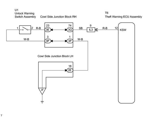
INSPECTION PROCEDURE
HINT:
When using the intelligent tester, start from *1. When not using the intelligent tester, start from *2.
PROCEDURE
|
1. |
READ VALUE USING INTELLIGENT TESTER (UNLOCK WARNING SWITCH ASSEMBLY) *1 |
(a) Check the DATA LIST for proper functioning of the unlock warning switch.
Theft warning ECU assembly:
|
Item |
Measurement Item / Display (Range) |
Normal Condition |
Diagnostic Note |
|---|---|---|---|
|
KEY SW |
Unlock warning switch signal / ON or OFF |
OFF: No key is in ignition key cylinder ON: Key is in ignition key cylinder |
- |
OK:
ON (key is in ignition key cylinder) appears on screen.
| OK |

|
PROCEED TO NEXT CIRCUIT INSPECTION SHOWN ON PROBLEM SYMPTOMS TABLE |
|

|
2. |
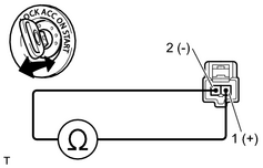
INSPECT UNLOCK WARNING SWITCH ASSEMBLY *2 |
(a) Remove the switch.
|
(b) Measure the resistance of the switch. Standard resistance:
|
|
| NG |
|
|
|
3. |
CHECK WIRE HARNESS (UNLOCK WARNING SWITCH - THEFT WARNING ECU AND BODY GROUND) |
(a) Disconnect the U1 switch connector.
(b) Disconnect the T6 ECU connector.
(c) Measure the resistance of the wire harness side connectors.
Standard resistance:
|
Tester Connection |
Specified Condition |
|---|---|
|
U1-2 - T6-12 (KSW) |
Below 1 Ω |
|
U1-1 - Body ground |
HINT:
When there is a malfunction that the theft deterrent system cannot be set, proceed to the next circuit inspection shown on the problem symptoms table before replace the theft warning ECU assembly.
| NG |
|
| OK |
|
PROCEED TO NEXT CIRCUIT INSPECTION SHOWN ON PROBLEM SYMPTOMS TABLE |

|

|