| Last Modified: 7-3-2017 | 6.8:8.0.40 | Doc ID: RM0000018H0003X |
| Model Year Start: 2007 | Model: LX470 | Prod Date Range: [08/2006 - ] |
| Title: THEFT DETERRENT: THEFT DETERRENT SYSTEM: Security Indicator Light Circuit; 2007 MY LX470 [08/2006 - ] | ||
|
Security Indicator Light Circuit |
DESCRIPTION
When the theft deterrent system is preparing to be set, the security indicator light turns ON. When the system is set, the security indicator light blinks. It also indicates the condition of the engine immobiliser system according to the request from the transponder key ECU assembly.
WIRING DIAGRAM
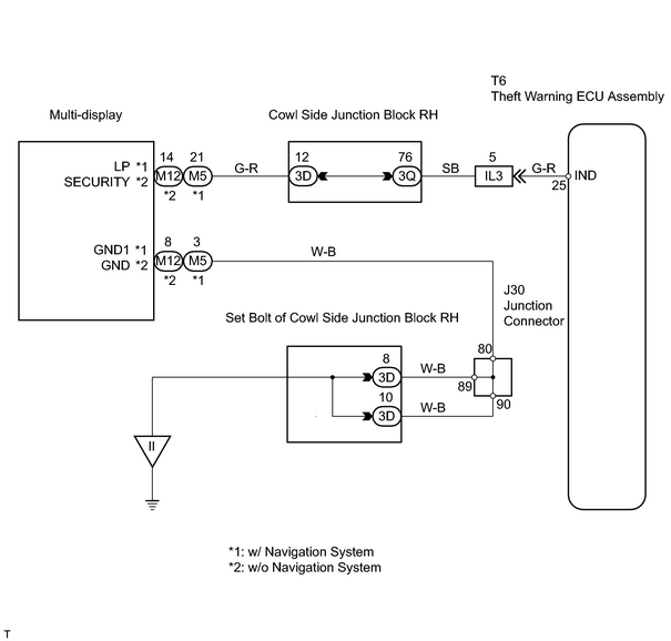
INSPECTION PROCEDURE
HINT:
When using the intelligent tester, start from *1. When not using the intelligent tester, start from *2.
PROCEDURE
|
1. |
PERFORM ACTIVE TEST USING INTELLIGENT TESTER (SECURITY INDICATOR LIGHT) *1 |
(a) Select the ACTIVE TEST, use the intelligent tester to generate a control command, and then check the security indicator light operation.
Theft warning ECU assembly:
|
Item |
Test Details |
Diagnostic Note |
|---|---|---|
|
SECURITY INDIC |
Turns security indicator light ON / OFF |
- |
OK:
The security indicator light turns ON or OFF in accordance with the tester command.
| OK |

|
PROCEED TO NEXT CIRCUIT INSPECTION SHOWN ON PROBLEM SYMPTOMS TABLE |
|

|
2. |
CHECK WIRE HARNESS (MULTI DISPLAY - THEFT WARNING ECU ASSEMBLY AND BODY GROUND) *2 |
(a) Disconnect the M5*1 or M12*2 connector.
HINT:
*1: w/ Navigation system
*2: w/o Navigation system
(b) Disconnect the T6 ECU connector.
(c) Measure the resistance of the wire harness side connectors.
Standard resistance:
w/ Navigation system
w/o Navigation system
|
Tester Connection |
Specified Condition |
|---|---|
|
M5-21 (LP) - T6-25 (IND) |
Below 1 Ω |
|
M5-3 (GND1) - Body ground |
|
Tester Connection |
Specified Condition |
|---|---|
|
M12-14 (SECURITY) - T6-25 (IND) |
Below 1 Ω |
|
M12-8 (GND) - Body ground |
| NG |
|
|
|
3. |
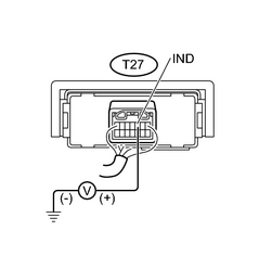
INSPECT TRANSPONDER KEY ECU ASSEMBLY |
(a) Turn the ignition switch OFF and set the theft deterrent system.
|
(b) Measure the voltage of the connector. Standard voltage: w/ Navigation system w/o Navigation system
|
|
| NG |
|
| OK |
|
Go to NAVIGATION SYSTEM (w/ NAVIGATION SYSTEM), MULTI-DISPLAY (w/o NAVIGATION SYSTEM) |

|

|