| Last Modified: 7-3-2017 | 6.8:8.0.40 | Doc ID: RM0000018L4009X |
| Model Year Start: 2007 | Model: LX470 | Prod Date Range: [08/2006 - ] |
| Title: TIRE AND WHEEL: TIRE PRESSURE WARNING SYSTEM: DIAGNOSIS SYSTEM; 2007 MY LX470 [08/2006 - ] | ||
DIAGNOSIS SYSTEM
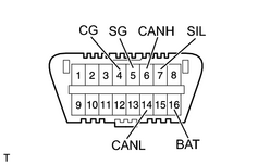
1. CHECK DLC3
|
(a) The vehicle's ECU uses ISO 15765-4 for communication. The terminal arrangement of the DLC3 complies with SAE J1962 and matches the ISO 15765-4 format.
NOTICE: *: Before measuring the resistance, leave the vehicle as is for at least 1 minute and do not operate the ignition switch, any other switches or the doors. If the result is not as specified, the DLC3 may have a malfunction. Repair or replace the harness and connector. HINT: Connect the cable of the intelligent tester to the DLC3, turn the ignition switch ON and attempt to use the tester. If the display indicates that a communication error has occurred, there is a problem either with the vehicle or with the tester.
|
|
2. DIAGNOSIS SYSTEM
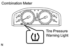
(a) Warning light
|
(1) The tire pressure warning light blinks when there is any malfunction in the tire pressure warning system. NOTICE: When the malfunction has been corrected, the tire pressure warning light does not come on. |
|
(b) DTCs (Normal mode)
(1)
DTCs are memorized in the tire pressure warning ECU and receiver. These DTCs can be read by checking the blinks of the tire pressure warning light or by using the intelligent tester
![2007 MY LX470 [08/2006 - ]; TIRE AND WHEEL: TIRE PRESSURE WARNING SYSTEM: DTC CHECK / CLEAR](../../../../stylegraphics/info.gif "2007 MY LX470 [08/2006 - ]; TIRE AND WHEEL: TIRE PRESSURE WARNING SYSTEM: DTC CHECK / CLEAR") .
.
(c) Test mode
(1)
By switching from normal mode to test mode (input signal check), you can inspect the tire pressure warning antenna, each tire pressure warning valve and transmitter and each vehicle speed sensor
.
3. CHECK WARNING LIGHT
|
(a) Turn the ignition switch ON. |
|
(b) Check that the tire pressure warning light comes on for 3 seconds.
If the warning check result is not normal, proceed to the troubleshooting for the tire pressure warning light circuit.
|
Trouble Area |
See page |
|---|---|
|
Tire pressure warning light circuit |
|
4. TIRE PRESSURE WARNING LIGHT CHART
HINT:
The table below indicates the state of the tire pressure warning light after the ignition switch is turned ON.
|
Immediately after turning the ignition switch ON |
Always |
|||||
|---|---|---|---|---|---|---|
|
Warning light output pattern |
||||||
|
Turns on for 3 sec. |
Goes off |
Turns on |
Blinks (*1) |
Blinks (*2) |
Blinks (*3) |
|
|
Normal |
○ |
○ |
- |
- |
- |
- |
|
Low tire pressure |
○ |
- |
○ |
- |
- |
- |
|
System fail |
○ |
- |
- |
○ |
- |
- |
|
Test mode |
○ |
- |
- |
- |
○ |
- |
|
Initialization |
○ |
- |
- |
- |
- |
○ |
|
ECU connector poorly connected |
- |
- |
○ |
- |
- |
- |
|
TC ground |
○ |
- |
- |
- |
- |
- |
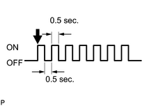
- *1: Comes on and goes off repeatedly at 0.5 second intervals.
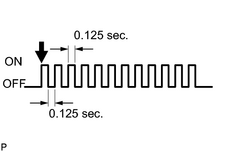
- *2: Comes on and goes off repeatedly at 0.125 second intervals.
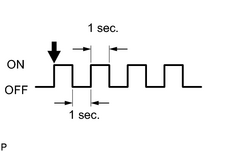
- *3: Blinks 3 times (1 second on, 1 second off).

|

|