| Last Modified: 7-3-2017 | 6.8:8.0.40 | Doc ID: RM0000018LW009X |
| Model Year Start: 2007 | Model: LX470 | Prod Date Range: [08/2006 - ] |
| Title: TIRE AND WHEEL: TIRE PRESSURE WARNING SYSTEM: Tire Pressure Warning Light Circuit; 2007 MY LX470 [08/2006 - ] | ||
|
Tire Pressure Warning Light Circuit |
DESCRIPTION
If the ECU detects trouble, the tire pressure warning light turns on and the tire pressure monitor is canceled at the same time. At this time, the ECU records a DTC in the memory.
Connecting terminals TC and CG of the DLC3 makes the tire pressure warning light blink and output the DTC.
WIRING DIAGRAM
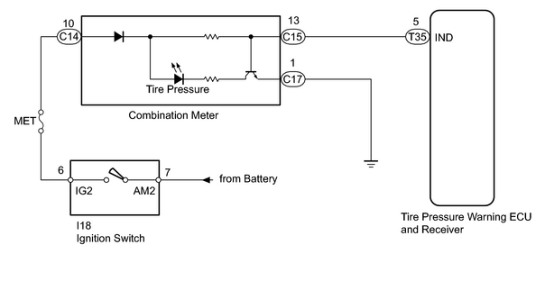
INSPECTION PROCEDURE
NOTICE:
- When replacing the tire pressure warning ECU and receiver, read the IDs stored in the old ECU using the intelligent tester and write them down before removal.
-
It is necessary to perform initialization
![2007 MY LX470 [08/2006 - ]; TIRE AND WHEEL: TIRE PRESSURE WARNING SYSTEM: INITIALIZATION](../../../../stylegraphics/info.gif "2007 MY LX470 [08/2006 - ]; TIRE AND WHEEL: TIRE PRESSURE WARNING SYSTEM: INITIALIZATION") after registration
of the transmitter IDs into the tire pressure warning ECU and receiver after the ECU has been replaced.
after registration
of the transmitter IDs into the tire pressure warning ECU and receiver after the ECU has been replaced.
PROCEDURE
|
1. |
INSPECT FUSE |
(a) Remove the MET fuse from the cowl side junction block RH.
(b) Measure the resistance according to the value(s) in the table below.
Standard resistance:
|
Tester Connection |
Condition |
Specified Condition |
|---|---|---|
|
MET fuse |
Always |
Below 1 Ω |
| OK |

|
|

|
2. |
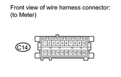
CHECK HARNESS AND CONNECTOR (METER - BODY GROUND) |
|
(a) Disconnect the C14 meter connector. (b) Measure the resistance according to the value(s) in the table below. Standard resistance:
|
|
| NG |
|
| OK |
|
|
3. |
CHECK HARNESS AND CONNECTOR (BATTERY - COMBINATION METER) |
|
(a) Disconnect the C14 combination meter connector. (b) Measure the voltage according to the value(s) in the table below. Standard voltage:
|
|
| NG |
|
|
|
4. |
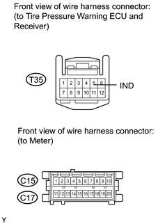
CHECK HARNESS AND CONNECTOR (COMBINATION METER - ECU AND BODY GROUND) |
|
(a) Disconnect the T35 ECU connector. |
|
(b) Disconnect the C15 and C17 meter connector.
(c) Measure the resistance according to the value(s) in the table below.
Standard resistance:
|
Tester Connection |
Condition |
Specified Condition |
|---|---|---|
|
T35-5 (IND) - C15-13 |
Always |
Below 1 Ω |
|
T35-5 (IND) - Body ground |
Always |
10 kΩ or higher |
|
C17-1 - Body ground |
Always |
Below 1 Ω |
| NG |
|
|
|
5. |
OPERATION OF ECU WITH NEW OR NORMAL FUNCTIONING ECU |
(a)
Temporarily replace the ECU with a new or normally functioning one
.
(b)
Perform registration
.
(c)
Perform initialization
after registration.
(d) Check that the malfunction disappears.
OK:
Malfunction disappears
| NG |
|
| OK |
|

|

|