- Stop light switch
- Harness or connector between ECM and stop light switch circuit
- ECM
| Last Modified: 7-3-2017 | 6.8:8.0.40 | Doc ID: RM0000018M3006X |
| Model Year Start: 2007 | Model: LX470 | Prod Date Range: [08/2006 - ] |
| Title: CRUISE CONTROL: CRUISE CONTROL SYSTEM: P0571/52; Brake Switch "A" Circuit; 2007 MY LX470 [08/2006 - ] | ||
|
DTC |
P0571/52 |
Brake Switch "A" Circuit |
DESCRIPTION
When the brake pedal is depressed, the stop light switch sends a signal to the ECM. When the ECM receives this signal, it cancels the cruise control.
A fail-safe function is provided so that the cancel functions normally, even if there is a malfunction in the stop light signal circuit.
The cancel condition is that battery positive voltage is supplied to terminal STP.
When the brake is applied, battery positive voltage is normally applied through the STOP fuse and stop light switch to terminal STP of the ECM, and the ECM turns the cruise control OFF.
If the harness connected to terminal STP has an open circuit, terminal STP will have battery positive voltage and the cruise control will be turned OFF.
|
DTC No. |
Detection Item |
Trouble Area |
|---|---|---|
|
P0571/52 |
Stop light switch circuit |
|
WIRING DIAGRAM
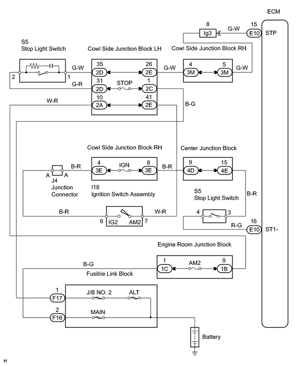
INSPECTION PROCEDURE
HINT:
In case of using the intelligent tester, start the inspection from *1 and in case of not using the intelligent tester, start from *2.
PROCEDURE
|
1. |
READ VALUE USING INTELLIGENT TESTER*1 |
(a) Connect the intelligent tester (with CAN VIM) to the DLC3.
(b) Turn the ignition switch ON and push the intelligent tester main switch ON.
(c) Select the item "STOP LIGHT SW" in the DATA LIST and read the value displayed.
OK:
Brake pedal depressed: ON
Brake pedal released: OFF
| OK |

|
PROCEED TO NEXT CIRCUIT INSPECTION SHOWN IN PROBLEM SYMPTOMS TABLE |
|

|
2. |
CHECK STOP LIGHT SWITCH OPERATION*2 |
(a) Check that the stop light comes on when the brake pedal is depressed, and turns off when the brake pedal is released.
| NG |
|
|
|
3. |
CHECK ECM (STP, ST1- VOLTAGE) |
|
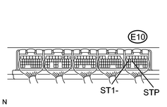
(a) Remove the ECM with the connectors still connected. (b) Turn the ignition switch ON. (c) Measure the voltage between terminal STP of the E10 ECM connector and body ground when the brake pedal is depressed and released. Standard voltage:
(d) Measure the voltage between terminal ST1- of the E9 ECM connector and body ground when the brake pedal is depressed and released. Standard voltage:
|
|
| OK |
|
PROCEED TO NEXT CIRCUIT INSPECTION SHOWN IN PROBLEM SYMPTOMS TABLE |
|
|
4. |
CHECK WIRE HARNESS (STOP LIGHT SWITCH - ECM AND BODY GROUND) |
| NG |
|
| OK |
|

|

|