- Front room temperature sensor
- Harness or connector between front room temperature sensor and A/C amplifier
- A/C amplifier
| Last Modified: 7-3-2017 | 6.8:8.0.40 | Doc ID: RM0000018MW004X |
| Model Year Start: 2007 | Model: LX470 | Prod Date Range: [08/2006 - ] |
| Title: AIR CONDITIONING: AIR CONDITIONING SYSTEM: 11; Room Temperature Sensor Circuit; 2007 MY LX470 [08/2006 - ] | ||
|
DTC |
11 |
Room Temperature Sensor Circuit |
DESCRIPTION
This sensor detects the temperature inside the cabin (front side) and sends the appropriate signals to the A/C amplifier.
|
DTC No. |
Detection Item |
Trouble Area |
|---|---|---|
|
11 |
Open or short in front room temperature sensor circuit |
|
WIRING DIAGRAM
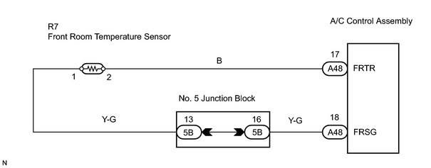
INSPECTION PROCEDURE
PROCEDURE
|
1. |
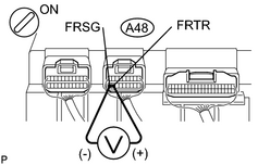
CHECK VOLTAGE BETWEEN TERMINALS FRTR AND FRSG OF AIR CONDITIONING AMPLIFIER |
|
(a) Remove the A/C amplifier with the connectors still connected. (b) Turn the ignition switch ON. (c) Measure the voltage between terminals FRTR (A48-17) and FRSG (A48-18) of A/C amplifier connector at each temperature. Standard voltage: 1.8 to 2.2 V at 25°C (77°F) 1.2 to 1.6 V at 40°C (104°F) HINT:
|
|
| OK |

|
|

|
2. |
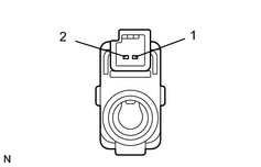
INSPECT FRONT ROOM TEMPERATURE SENSOR |
|
(a) Disconnect the R7 front room temperature sensor connector. (b) Measure the resistance between terminals 1 and 2 the of front room temperature sensor connector at each temperature. Standard resistance: 1.65 to 1.75 kΩ at 25°C (77°F) 0.55 to 0.65 kΩ at 50°C (122°F) HINT: As the temperature increases, the resistance decreases. |
|
| NG |
|
|
|
3. |
CHECK WIRE HARNESS (AIR CONDITIONING AMPLIFIER - FRONT ROOM TEMPERATURE SENSOR) |
| NG |
|
| OK |
|

|

|