- Solar sensor
- Harness or connector between solar sensor and A/C amplifier
- A/C amplifier
| Last Modified: 7-3-2017 | 6.8:8.0.40 | Doc ID: RM0000018N4004X |
| Model Year Start: 2007 | Model: LX470 | Prod Date Range: [08/2006 - ] |
| Title: AIR CONDITIONING: AIR CONDITIONING SYSTEM: 21; Solar Sensor Circuit; 2007 MY LX470 [08/2006 - ] | ||
|
DTC |
21 |
Solar Sensor Circuit |
DESCRIPTION
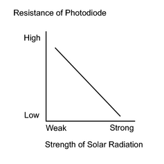
A photodiode in the solar sensor detects solar radiation and sends signals to the A/C amplifier.
|
DTC No. |
Detection Item |
Trouble Area |
|---|---|---|
|
21 |
Open or short in solar sensor circuit Please note that display of diagnostic trouble code 21 is not abnormal when the sensor is not receiving solar radiation |
|
WIRING DIAGRAM
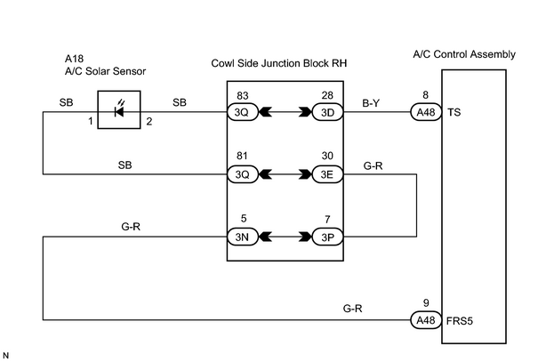
INSPECTION PROCEDURE
PROCEDURE
|
1. |
CHECK AIR CONDITIONING AMPLIFIER |
|
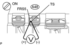
(a) Remove the A/C amplifier with the connectors still connected. (b) Turn the ignition switch ON. (c) Measure the voltage between terminals FRS5 (A48-9) and TS (A48-8) of the A/C amplifier connector when the solar sensor is subjected to an electric light, and when the sensor is covered with a cloth. Standard voltage:
HINT:
|
|
| OK |

|
|

|
2. |
CHECK SOLAR SENSOR |
|
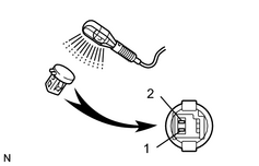
(a) Remove the solar sensor. (b) Connect the positive (+) lead of ohmmeter to terminal 2 and negative (-) lead to terminal 1 of the solar sensor. (c) Measure the resistance between terminals 1 and 2 of the solar sensor connector. Standard resistance:
NOTICE: The connection procedure for a digital tester, such as a TOYOTA electrical tester, is shown above. When using an analog tester, connect the negative (-) lead to terminal 1 and positive (+) lead to terminal 2. HINT:
|
|
| NG |
|
|
|
3. |
CHECK WIRE HARNESS (AIR CONDITIONING AMPLIFIER - SOLAR SENSOR) |
| NG |
|
| OK |
|

|

|