- Air inlet damper position sensor
- Harness or connector between air inlet damper position sensor and A/C amplifier
- A/C amplifier
| Last Modified: 7-3-2017 | 6.8:8.0.40 | Doc ID: RM0000018NA004X |
| Model Year Start: 2007 | Model: LX470 | Prod Date Range: [08/2006 - ] |
| Title: AIR CONDITIONING: AIR CONDITIONING SYSTEM: 32,42; Air Inlet Damper Position Sensor Circuit; 2007 MY LX470 [08/2006 - ] | ||
|
DTC |
32 |
Air Inlet Damper Position Sensor Circuit |
|
DTC |
42 |
Air Inlet Damper Control Servo Motor Circuit |
DESCRIPTION
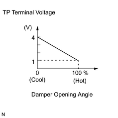
This sensor detects the position of the air inlet damper and sends the appropriate signals to the A/C amplifier.
The position sensor is built into the air inlet servo motor.
|
DTC No. |
Detection Item |
Trouble Area |
|---|---|---|
|
32 |
Short to ground or to power source circuit in air inlet damper position sensor circuit |
|
|
42 |
Air inlet damper position sensor value does not change even if A/C amplifier operates air inlet damper control servo motor |
WIRING DIAGRAM
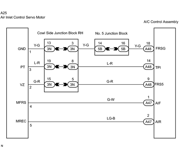
INSPECTION PROCEDURE
PROCEDURE
|
1. |
CHECK AIR CONDITIONING AMPLIFIER |
|
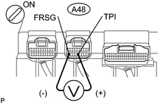
(a) Remove the A/C amplifier with the connectors still connected. (b) Turn the ignition switch ON. (c) Press the REC/FRS switch to change air inlet between fresh and recirculation air, and measure the voltage between terminals TPI (A48-14) and FRSG (A48-18) of the A/C amplifier when the air inlet servo motor operates. Standard voltage:
HINT:
|
|
| OK |

|
|

|
2. |
CHECK AIR INLET DAMPER POSITION SENSOR |
|
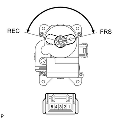
(a) Remove the air inlet servo motor. (b) Measure the resistance between terminals 1 (GND) and 3 (PT) of the air inlet damper control servo motor connector. Standard resistance: 4.2 to 7.8 kΩ (c)
While operating the air inlet damper control servo motor, follow the procedure on page (
Standard resistance:
HINT: As the air inlet servo motor moves from REC side to FRS side, the resistance decreases. |
|
![2007 MY LX470 [08/2006 - ]; AIR CONDITIONING: AIR CONDITIONING SYSTEM: 42; Air Inlet Damper Control Servo Motor Circuit](../../../../stylegraphics/info.gif "2007 MY LX470 [08/2006 - ]; AIR CONDITIONING: AIR CONDITIONING SYSTEM: 42; Air Inlet Damper Control Servo Motor Circuit")
| NG |
|
|
|
3. |
CHECK WIRE HARNESS (AIR INLET DAMPER POSITION SENSOR - AIR CONDITIONING AMPLIFIER) |
| NG |
|
| OK |
|

|

|