
- A/C SW Push: ON
- A/C SW Release: OFF
| Last Modified: 7-3-2017 | 6.8:8.0.40 | Doc ID: RM0000018NH005X |
| Model Year Start: 2007 | Model: LX470 | Prod Date Range: [08/2006 - ] |
| Title: AIR CONDITIONING: AIR CONDITIONING SYSTEM: Compressor Circuit; 2007 MY LX470 [08/2006 - ] | ||
|
Compressor Circuit |
DESCRIPTION
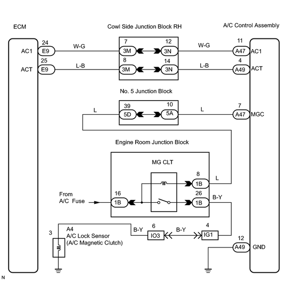
The A/C amplifier outputs the magnetic clutch ON signal from terminal ACT to the ECM. When the ECM receives this signal, it sends a signal from terminal MGC and switches the A/C magnetic clutch relay ON, thus turning on the A/C magnetic clutch.
WIRING DIAGRAM
INSPECTION PROCEDURE
HINT:
When using the intelligent tester, start from *1. When not using the intelligent tester, start from *2.
PROCEDURE
|
1. |
PERFORM ACTIVE TEST USING INTELLIGENT TESTER*1 |
(a) Connect the intelligent tester (with CAN VIM) to the DLC3.
(b) Turn the ignition switch ON and push the intelligent tester main switch ON.
(c) Select the item "A/C MAG CLUTCH" in the ACTIVE TEST and read its value displayed on the intelligent tester.
OK
|
Item |
Measurement Item/Display (Range) |
Diagnostic Note |
|---|---|---|
|
A/C MAG CLUTCH |
A/C Magnet Clutch Status/ON or OFF |
- |
HINT:
Check with the engine running.
| NG |

|
|
|
2. |
READ VALUE USING INTELLIGENT TESTER |
(a) Connect the intelligent tester (with CAN VIM) to the DLC3.
(b) Turn the ignition switch ON and push the intelligent tester main switch ON.
(c) Select the item "A/C SIG" in the DATA LIST and read its value displayed on the intelligent tester.
|
Item |
Measurement Item/Display (Range) |
Normal Condition |
Diagnostic Note |
|---|---|---|---|
|
A/C SIG |
A/C SW Status/ON or OFF |
|
- |
| NG |
|
| OK |
|
|
3. |
INSPECT MAGNETIC CLUTCH RELAY*2 |
|
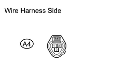
(a) Disconnect the A4 magnetic clutch connector. |
|
(b) Turn the ignition switch ON.
(c) Push the A/C switch ON.
(d) Measure the voltage of the wire harness side connectors.
Standard voltage:
|
Tester Connection |
Specified Condition |
|---|---|
|
A4 - 3 - Body ground |
10 to 14 V |
| OK |
|
|
|
4. |
INSPECT FUSE (A/C) |
(a) Remove the A/C fuse from the cowl side junction block LH.
(b) Measure the resistance of the fuse.
OK:
Below 1 Ω
| NG |
|
|
|
5. |
CHECK WIRE HARNESS (BATTERY - MAGNETIC CLUTCH RELAY) |
|
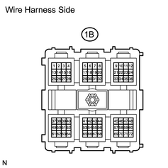
(a) Disconnect the 1B engine room junction block connector. (b) Turn the ignition switch ON. (c) Measure the voltage of the wire harness side connectors. Standard voltage:
|
|
| NG |
|
|
|
6. |
CHECK WIRE HARNESS (AIR CONDITIONING AMPLIFIER - MAGNETIC CLUTCH RELAY) |
|
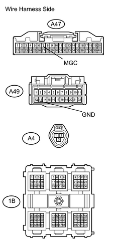
(a) Disconnect the 1B engine room junction block connector. (b) Disconnect the A47 and A49 A/C amplifier connector. (c) Disconnect the A4 magnetic clutch connector. (d) Measure the resistance of the wire harness side connectors, Standard resistance:
|
|
| NG |
|
|
|
7. |
CHECK MAGNETIC CLUTCH RELAY |
(a) Disconnect the 1B engine room junction block connector.
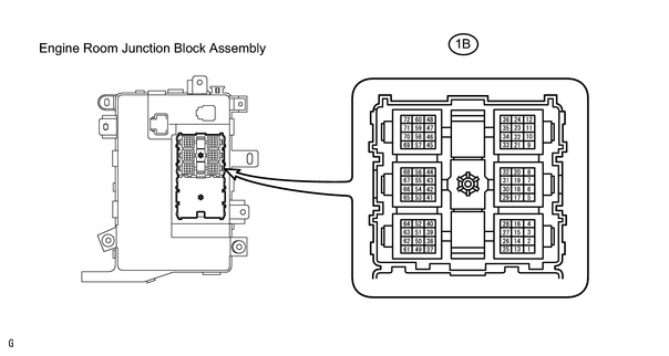
(b) Measure the resistance of the relay.
Standard resistance:
|
Tester Connection |
Specified Condition |
|---|---|
|
1B-16 - 1B-26 |
10 k Ω or higher |
|
1B-16 - 1B-26 |
Below 1 Ω (When battery voltage is applied to terminals 1B-16 and 1B-8.) |
| NG |
|
|
|
8. |
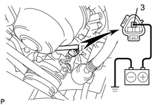
CHECK MAGNETIC CLUTCH ASSEMBLY |
|
(a) Disconnect the magnetic clutch connector. |
|
(b) Connect the positive (+) lead connected to the battery to the magnetic clutch connector terminal 3 and check the magnetic clutch.
OK:
Magnetic clutch is energized.
| NG |
|
|
|
9. |
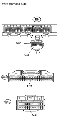
CHECK WIRE HARNESS (AIR CONDITIONING AMPLIFIER - ECM) |
|
(a) Disconnect the A47 and A49 A/C amplifier connectors. |
|
(b) Disconnect the E9 ECM connector.
(c) Measure the resistance of the wire harness side connectors.
Standard resistance:
|
Tester Connection |
Specified Condition |
|---|---|
|
A47-11 (AC1) - E9-24 (AC1) |
Below 1 Ω |
|
A47-11 (AC1) - Body ground |
10 k Ω or higher |
|
A49-4 (ACT) - E9-25 (ACT) |
Below 1 Ω |
|
A49-4 (ACT) - Body ground |
10 k Ω or higher |
| NG |
|
|
|
10. |
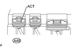
CHECK AIR CONDITIONING AMPLIFIER |
|
(a) Remove the A/C amplifier with connectors still connected. |
|
(b) Start the engine and push AUTO switch.
(c) Measure the voltage of the A/C amplifier connector and body ground when magnetic clutch is ON and OFF by A/C switch.
Standard voltage:
|
Switch Condition |
Tester Connection |
Specified Condition |
|---|---|---|
|
ON |
A49-4 (ACT) - Body ground |
10 to 14 V |
|
OFF |
A49-4 (ACT) - Body ground |
Below 1 V |
| NG |
|
| OK |
|

|

|